Coupling device for producing and separating an energy-transferring plug-in connection and energy input system having such a coupling device

Active Publication Date: 2018-05-24
AUDI AG
View PDF2 Cites 0 Cited by
  • Summary
  • Abstract
  • Description
  • Claims
  • Application Information

AI Technical Summary

Benefits of technology

[0013]In accordance with an enhancement of the invention, it is provided that the coupling device has a diverting device, which is equipped to divert the plug from its tilted position, that is, in particular from the position of rest, to the plug-in position aligned in the plug-in direction. Preferably, the diverting device is also equipped additionally to divert the plug conversely from its plug-in position to its tilted position of rest. The diverting device makes it possible in a simple and secure way to pivot the plug from its tilted position to its plug-in position and vice versa. In particular, the plug is diverted by the diverting device in the way described when it is driven by t

Problems solved by technology

This is a drawback, in particular, when the coupling device is intended to be suitable for producing a plug-in connection in the area of the underbody of a motor vehicle and to be capable of being shifted for this purpose unde

Method used


Image

  • Coupling device for producing and separating an energy-transferring plug-in connection and energy input system having such a coupling device
  • Coupling device for producing and separating an energy-transferring plug-in connection and energy input system having such a coupling device
  • Coupling device for producing and separating an energy-transferring plug-in connection and energy input system having such a coupling device

Examples


Embodiment Construction

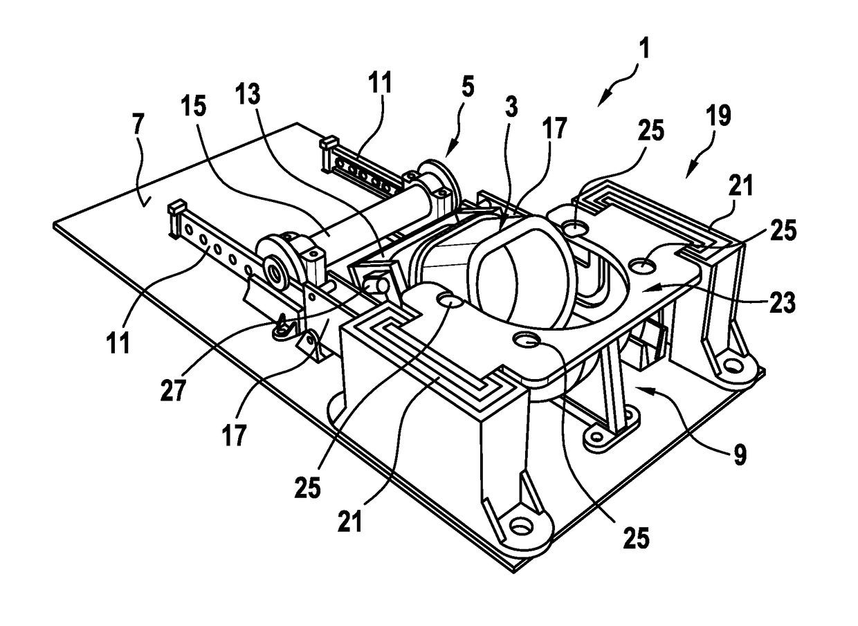
[0045]FIG. 1 shows a schematic illustration of an exemplary embodiment of a coupling device 1, which is equipped for producing and separating an energy-transferring—preferably electrical—plug-in connection, which has shiftable plug 3, which can be inserted along a plug-in direction into a corresponding plug receptacle, which is not illustrated, as well as a drive device 5, wherein the drive device 5 is operatively connected to the plug 3 for shifting thereof. In a decoupled state of the coupling device 1, which is illustrated in FIG. 1, in which said plug is not inserted in the plug receptacle, the plug 3 can thereby be arranged, in the position of rest, at a tilt with respect to the plug-in direction. The plug-in direction extends here, in particular perpendicularly to a bottom plane 7 of the coupling device 1. Owing to the tilted arrangement of the plug 3 with respect to the plug-in direction in the position of rest, the coupling device 1 can be designed to be especially small in ...


PUM


Abstract

A coupling device for producing and separating an energy-transferring plug-in connection, having a plug that can be shifted along a plug-in direction for insertion into a corresponding plug receptacle, and having a drive device, which is operatively connected to the plug for the shifting thereof. In a decoupled state of the coupling device, the plug can be arranged in a position of rest at a tilt with respect to the plug-in direction.

Description

FIELD[0001]The invention relates to a coupling device for producing and separating an energy-transferring plug-in connection and an energy input system for inputting energy into a motor vehicle having such a coupling device.BACKGROUND[0002]Rod arrangements or lever arrangements are usually used, particularly for the automatic production and separation of plug-in connections, in order to shift a plug linearly in the plug-in direction. Mechanical arrangements that are suitable for this purpose require a large structured space in the plug-in direction. Because the plug, in particular together with its plug head, has to protrude completely from the mechanism in order to be inserted correctly into a corresponding plug receptacle, such as, for example, a plug socket, it is necessary to incorporate the fastening of the mechanism at the plug as well as the application of force by way of the mechanism into the plug below the plug head. Accordingly, the structural height of the mechanism over...

Claims


Application Information

Patent Timeline
IPC IPC(8): B60L11/18H01R13/71H01R13/62H01R13/453
CPCB60L11/1818B60L11/1809H01R13/71H01R13/6205H01R13/4532H01R13/4534G07F15/005H01M10/44H01R13/631H01R2201/26B60L53/16H01R13/4536H01R13/6315Y02E60/10Y02T10/70Y02T10/7072Y02T90/14
Inventor KUPFER, ALEXANDERGKOUMAS, ILIAS
Owner AUDI AG
Why Eureka
Try Eureka