Method for repairing defects in a metallic substrate using welding

a technology of metallic substrate and repair method, which is applied in the direction of welding apparatus, manufacturing tools, cooking vessels, etc., can solve the problems of high repair cost, frequent repair of damaged, corroded, or worn parts, and reduce the cost of repairing defects. , the effect of reducing the cost of repairing defects

Active Publication Date: 2005-08-11
EDISON WELDING INSTITUTE INC
View PDF18 Cites 18 Cited by
  • Summary
  • Abstract
  • Description
  • Claims
  • Application Information

AI Technical Summary

Benefits of technology

[0016] Unlike other repair techniques, the consumable filler slug and metallic substrate material surrounding the resistively heated area prevent oxidation. Therefore, this method does not require the use of a shielding gas, thereby reducing the cost of repairing defects as well increasing the versatility of the method. Additionally, the incorporation of a sacrificial retainer creates the ability to further seal the substantially liquid pool from the surrounding atmosphere, if desired. Further, the sacrificial retainer tends to keep the electrodes clean. In such an embodiment, the sacrificial retainer is placed between the slug and the first electrode through which the current passes and resistively heats. A portion of the sacrificial retainer coalesces into the pool and a portion of the sacrificial retainer remains solid and constrains the flow of the pool and seals the pool from the surrounding atmosphere. The portion of the sacrificial retainer that remains solid, and any portion of the solidified pool, may be removed by finishing processes to bring the level of the repaired defect down to the level of the adjoining metallic substrate. The method may be performed such that the electrical current is substantially uniformly transmitted from the first electrode to the second electrode. Such uniform transmission results in substantially symmetric resistive heating of the slug and the metallic substrate and substantially uniform heating of the defect, unlike previous defect repair techniques having non-symmetric thermal profiles around the defect during repair and solidification. The application of nearly uniform heat around the entire perimeter of the defect substantially helps eliminate distortion.
[0017] With the instant invention, the period of the heat input and the amount of heat input of the present invention is significantly less than that of previous defect repair techniques. Further, the amount of heat that remains in the repaired metallic substrate is significantly less using the method of the present invention, as will be discussed later herein, further reducing distortion and improving performance of the repaired defect.
[0018] The substantially liquid pool is then cooled to solidification. The pressure exerted on the substantially liquid pool during solidification reduces contraction stresses during solidification of the pool since the fusion zone remains under compressive loading. This tends to prevent solidification and liquation cracks from forming in the repaired defect. The cooling of the liquid pool is generally accomplished by utilizing water cooled electrodes, but may be accomplished through the use of a number of heat transfer processes. The cooling of the pool, as well as the short period of heat input, produces a repaired metallic substrate containing very little residual heat. The small amount of residual heat in the repaired metallic substrate and rapid cooling of the substantially liquid pool further minimize distortion and significantly improve the performance of the repaired defect.

Problems solved by technology

Repairing defects in manufactured assemblies costs industries hundreds of millions of dollars each year.
In fact, many industries view repairing defects in assemblies constructed of relatively thin metallic sheet materials, and the very high cost of these repairs, as a necessary evil and have invested heavily in preventing such defects rather than identifying more cost effective ways to repair such defects.
The aircraft industry is just one of many industries plagued by this problem.
Additionally, the need frequently arises to repair damaged, corroded, or worn holes in parts that have already been in service for a period of time.
Additionally, no matter how skilled the welder, the very nature of arc welding results in a large amount of heat input that is applied asymmetrically over the defect to repair the defect.
As such, arc welding repairs have large heat affected zones that can influence mechanical and corrosion performance in the repair area.
The large heat affected zone often results in local distortion of the repaired substrate that then requires post-weld treatment to return the substrate to the desired tolerances.
A further limitation to arc welding repairs is the significant amount of pre and post weld preparation of the defect area required to produce a quality weld and ensure the desired part geometry is produced.
An even greater limitation introduced when using arc welding to repair defects is that the repair weld is often of less than optimal quality and that filler materials must often be used that reduce performance of the component to improve the weldability of the surrounding substrate.
This can result in repairs of significantly less strength than the surrounding substrate.
For instance, filler metals having very high ductility, but less than desired strength and corrosion properties, are often required to minimize solidification cracking when using arc welding to repair defects in materials that have been in use for a period of time and suffer from reduced ductility.
This is particularly true in the aircraft industry where holes often require repair after the aircraft has been in service for several years.
The friction plug welding process has some definite limitations, which are primarily associated with the need to apply and react the mechanical loads associated with this process.
The friction welding equipment used to produce the weld is typically very large due to the rotational energy that must be applied to the plug and the axial load necessary to force the plug into the tapered hole.
An additional limitation of friction plug welding is that it requires line of sight access to the repair area, thereby limiting it to only the most simple repairs.
Further, friction plug welding equipment is expensive and less readily available than arc welding or resistance welding equipment.

Method used


Image

  • Method for repairing defects in a metallic substrate using welding
  • Method for repairing defects in a metallic substrate using welding
  • Method for repairing defects in a metallic substrate using welding

Examples


Embodiment Construction

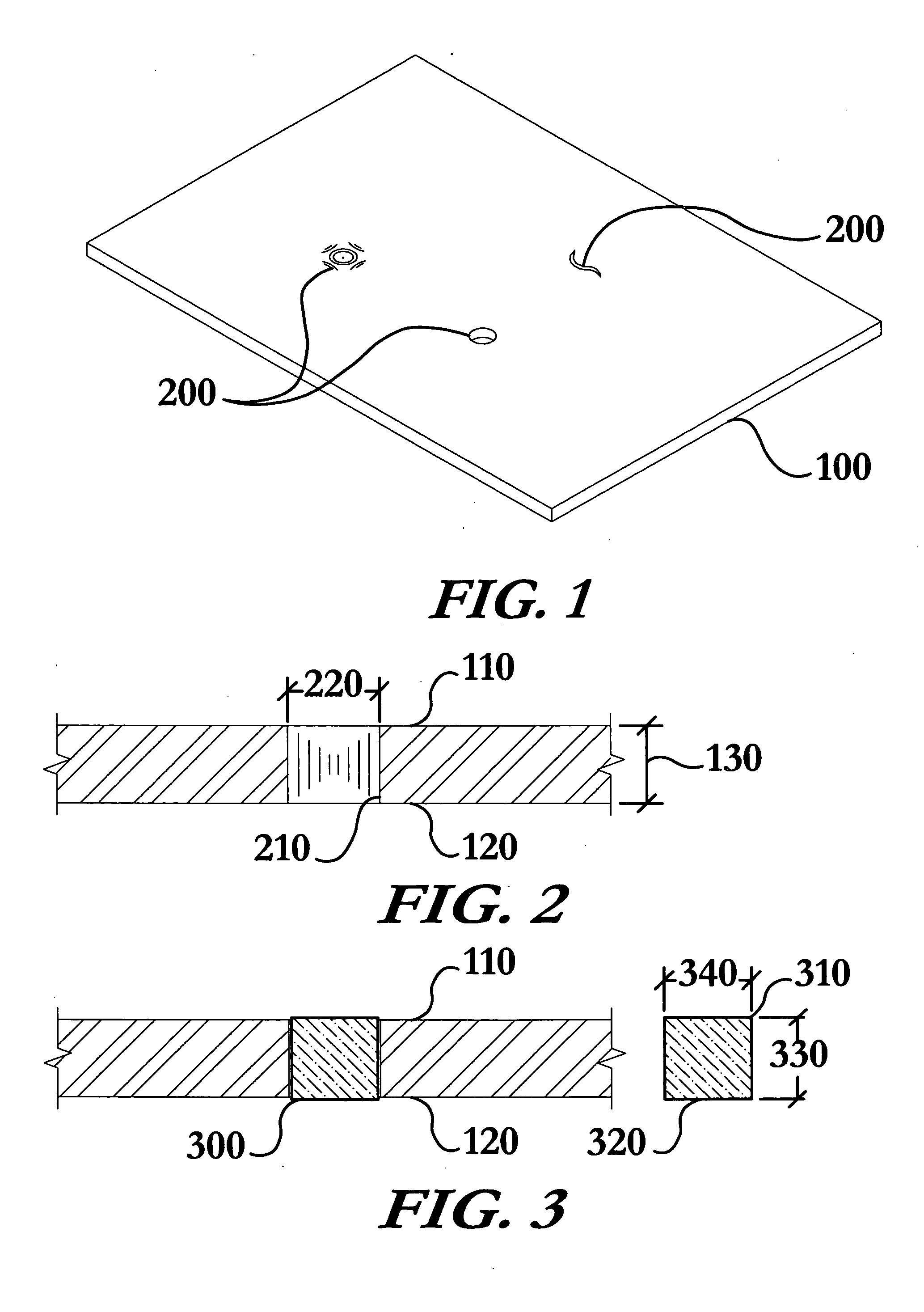
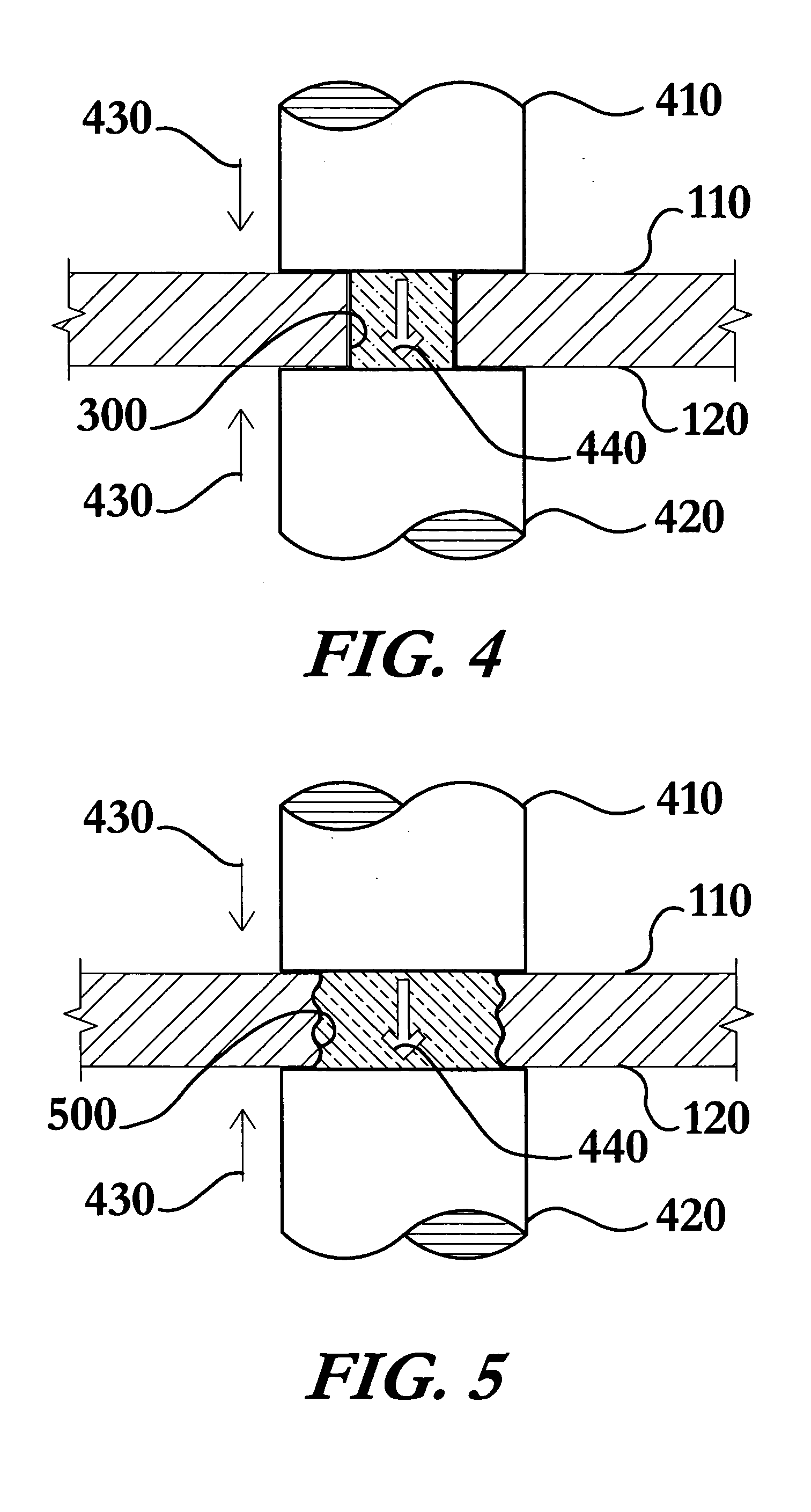
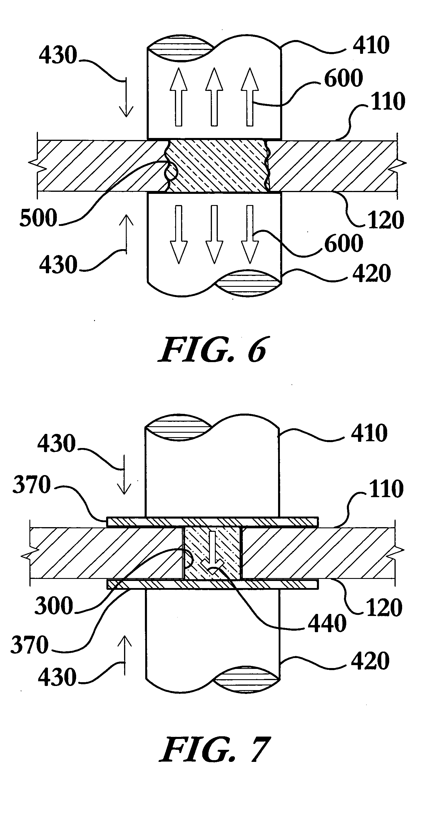
[0035] The method for repairing a defect in a metallic substrate using welding enables a significant advance in the state of the art. The preferred embodiments of the apparatus accomplish this by new and novel methods that are configured in unique and novel ways and which demonstrate previously unavailable but preferred and desirable capabilities. The description set forth below in connection with the drawings is intended merely as a description of the presently preferred embodiments of the invention, and is not intended to represent the only form in which the present invention may be constructed or utilized. The description sets forth the designs, functions, means, and methods of implementing the invention in connection with the illustrated embodiments. It is to be understood, however, that the same or equivalent functions and features may be accomplished by different embodiments that are also intended to be encompassed within the spirit and scope of the invention.

[0036] One exemp...


PUM

PropertyMeasurementUnit
fatigue strengthaaaaaaaaaa
yield strengthaaaaaaaaaa

Abstract

A method for repairing defects in a metallic substrate comprising the steps of placing a consumable filler slug in contact with the substrate in the vicinity of the defect; bringing a first electrode and a second electrode in contact with the consumable slug and applying a pressure to the consumable slug; and transmitting electrical current between the electrodes for a period, thereby resistively heating the consumable slug and the metallic substrate resulting in coalescence in a substantially liquid pool that fills the defect. The pool is then cooled to solidification under the pressure of the electrodes. The electrodes are then removed from contact with the consumable slug and excess material may be removed. The consumable slug may be formed as a single unit or multiple sections, and may incorporate sacrificial retainers to add additional defect filling material, retain the pool, and seal the pool from atmosphere.

Description

STATEMENT REGARDING FEDERALLY SPONSORED RESEARCH OR DEVELOPMENT [0001] This invention was not made as part of a federally sponsored research or development project. TECHNICAL FIELD [0002] The present invention relates to the field of material defect repair; particularly, to a method and apparatus for repairing material defects utilizing a consumable filler slug, electrical current, and pressure to resistively melt the slug and repair the defect. BACKGROUND OF THE INVENTION [0003] Repairing defects in manufactured assemblies costs industries hundreds of millions of dollars each year. In fact, many industries view repairing defects in assemblies constructed of relatively thin metallic sheet materials, and the very high cost of these repairs, as a necessary evil and have invested heavily in preventing such defects rather than identifying more cost effective ways to repair such defects. The aircraft industry is just one of many industries plagued by this problem. [0004] In the aircraft ...

Claims


Application Information

Patent Timeline
Patent Type & Authority Applications(United States)
IPC IPC(8): B23K1/00B23K1/20B23K11/10B23P6/00
CPCB23K11/0013B23K11/002B23K11/10B23K2201/18B23P6/00B23K2203/08B23K2203/10B23K2203/14B23K2203/02B23K2101/18B23K2103/02B23K2103/10B23K2103/14B23K2103/26
Inventor WORKMAN, DAVID P.REYNOLDS, JAMES L. JR.TRAPP, TIMOTHY J.GOULD, JERRY E.
Owner EDISON WELDING INSTITUTE INC
Why Eureka
Try Eureka