Light source module group

A technology of light source module and light guide plate, applied in the direction of light source, electric light source, point light source, etc., can solve the problem of inability to transmit large-area illumination, achieve uniform transmission, and improve the effect of light coupling efficiency

Inactive Publication Date: 2009-04-15
FOXSEMICON INTEGRATED TECHNOLOGY (SHANGHAI) INC +1
View PDF0 Cites 15 Cited by
  • Summary
  • Abstract
  • Description
  • Claims
  • Application Information

AI Technical Summary

Problems solved by technology

When the side surfaces of the light-emitting units are made sufficiently flat by high-cost grinding or other processing methods, or the air gap is less than 0.2 mm, the situation that light is blocked between two adjacent light-emitting units can be slightly alleviated, however, still It cannot meet the requirement of high light coupling efficiency between two adjacent light-emitting units, and cannot make light uniformly transmitted between two adjacent light-emitting units to meet large-area lighting

Method used


Image

  • Light source module group
  • Light source module group
  • Light source module group

Examples


Embodiment Construction

[0013] The embodiments of the present invention will be further described in detail below in conjunction with the accompanying drawings.

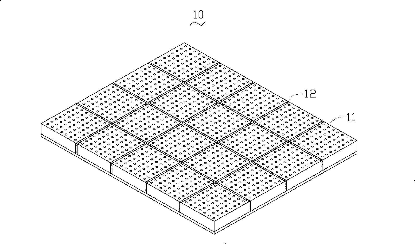
[0014] see figure 1 The light source module 10 provided by the first embodiment of the present invention includes a plurality of light emitting units 11 , and two adjacent light emitting units 11 in the plurality of light emitting units 11 are connected by a transparent adhesive 12 .

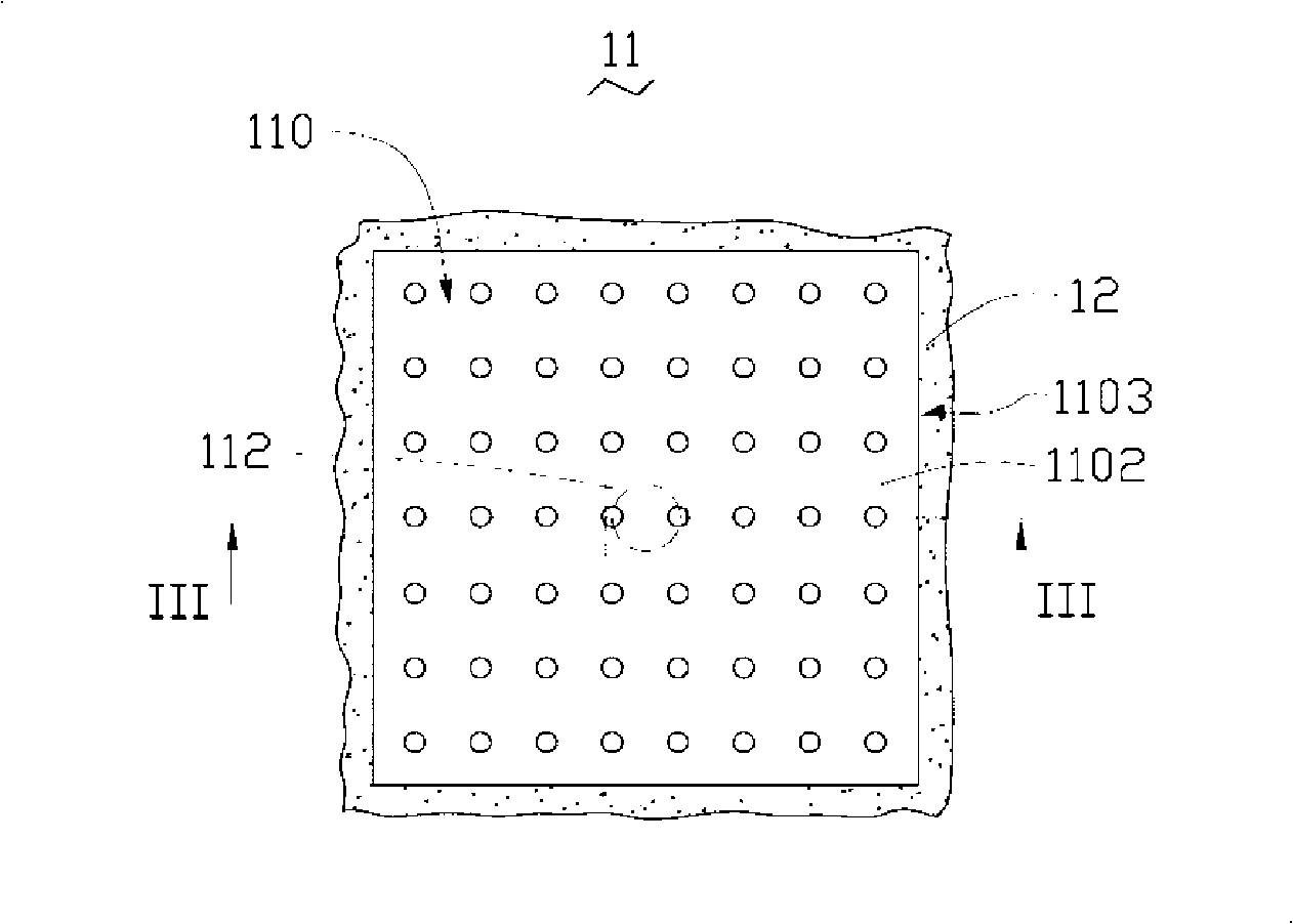
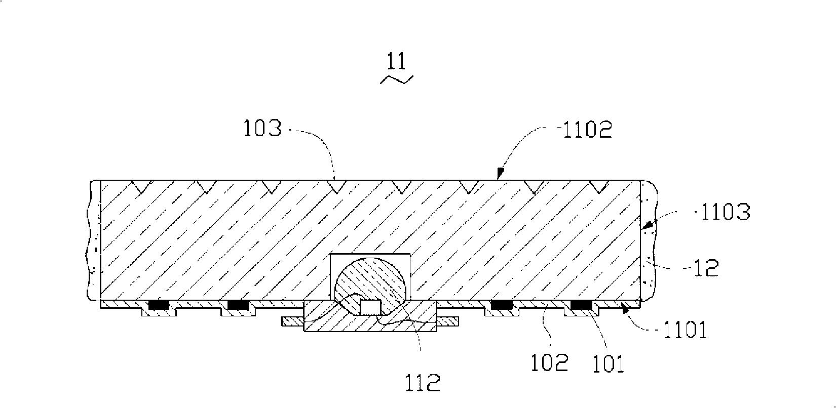
[0015] see figure 2 and image 3 , the light emitting unit 11 includes a light guide plate 110 and a light emitting element 112 optically coupled with the light guide plate 110 .

[0016] The light guide plate 110 includes a bottom surface 1101 , a light emitting surface 1102 opposite to the bottom surface 1101 , and a side surface 1103 disposed between the bottom surface 1101 and the light emitting surface 1102 . The shape of the light guide plate 110 can be square, triangular, regular hexagonal deformation and other shapes that are convenient for splici...


PUM


Abstract

The invention relates to a light source module which comprises multiple light emitting units, the multiple light emitting units respectively comprise a light guide plate and at least one light emitting component, the light guide plate is optically coupled with the at least one light emitting component, the light guide plate comprises a bottom surface, a light emitting surface opposite to the bottom surface, and a side face arranged between the bottom surface and the light emitting surface, and the side faces of two adjacent light guide plates are connected by transparent adhesive glue. In the light source module, the light guide plates of the two adjacent lighting units are bonded by the transparent adhesive glue, which causes the light rays to be evenly transmitted in the transparent adhesive glue and improves the optical coupling efficiency of the two adjacent light emitting units.

Description

technical field [0001] The invention relates to a light source module, in particular to a light source module with a plurality of light emitting units. Background technique [0002] Nowadays, light emitting diodes (Light Emitting Diode, LED) have been widely used in many fields. Because light emitting diodes have the characteristics of high luminous efficiency, long life, and good color rendering, they have begun to be used in many fields. Here, A new type of light-emitting diode can be found in the article "Illumination With Solid State Lighting Technology" in IEEE Journal on Selected Topics in Quantum Electronics, Vol.8, No.2, March / April 2002 by Daniel A. Steigerwald et al. [0003] Existing light source modules with light-emitting diodes, such as backlight panels, advertising light panels, etc., are often used in large-area display devices, so it is necessary to splice multiple light-emitting units each with light-emitting diodes together to provide Large area lighting....

Claims


Application Information

Patent Timeline
Patent Type & Authority Applications(China)
IPC IPC(8): G02B6/00G02F1/13357F21K7/00F21K99/00G02F1/1335
CPCG02B6/0043G02B6/0036G09F13/22F21V21/005F21S2/005G02B6/0055G02B6/0078F21Y2101/02F21Y2115/10
Inventor 王梦华锺丰丞徐弘光
Owner FOXSEMICON INTEGRATED TECHNOLOGY (SHANGHAI) INC
Why Eureka
Try Eureka