

Flexible strip for horology and method for manufacturing the same
- Summary
- Abstract
- Description
- Claims
- Application Information
AI Technical Summary
Benefits of technology
Problems solved by technology
Method used
Image

Examples
Embodiment Construction
[0060]The invention concerns the development of flexible strips for timepiece mechanisms, such as pivots, resonators, escapement mechanisms, or suchlike, with improved properties compared to existing flexible strips. In particular, the invention endeavors to obtain elastic flexible strips with a much higher aspect ratio than that of prior art strips.
[0061]The flexible strips according to the invention must be usable both in single level structures, and in more complex structures implementing several parallel levels.
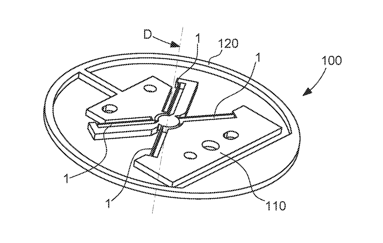
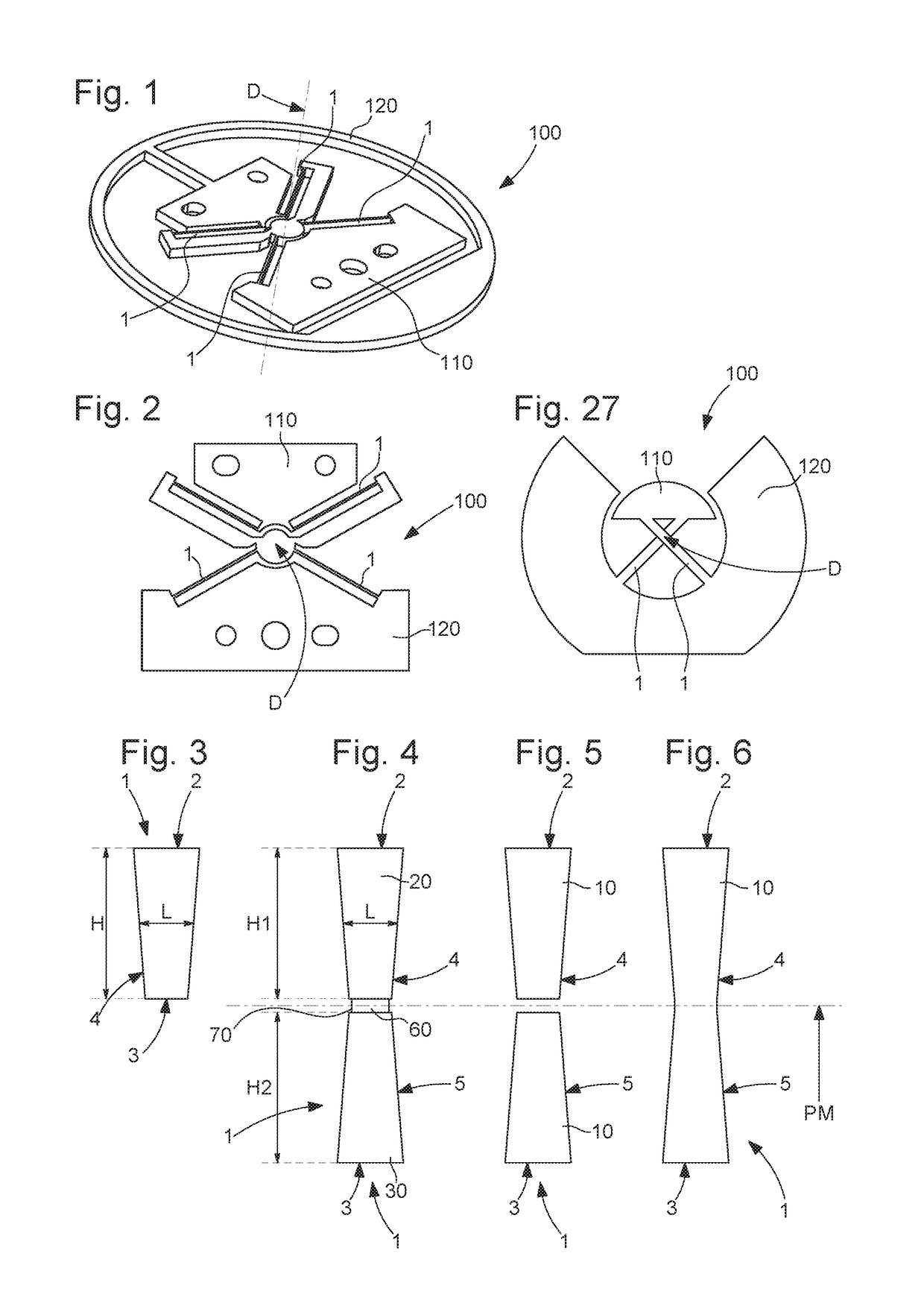
[0062]FIG. 1 represents a resonator with a single-level flexible pivot, comprising a fixed structure to which is fixed an inertial element via a flexible pivot, comprising such flexible strips.
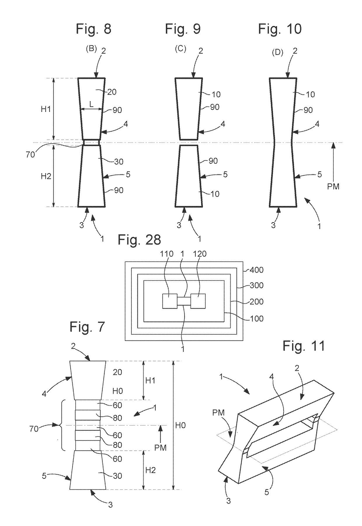
[0063]The invention is described below for a simplified application to a basic strip, especially, but not limited to a straight strip, and the features of the invention are also applicable to a more complex structure, in particular to a one-piece element, particularly made of microm...
PUM
 Abstract
Description
Claims
Application Information