
Thermostatic steam trap

a steam trap and steam technology, applied in steam traps, non-electric variable control, instruments, etc., can solve the problems of large size of steam trap assembly and general heavyness, and achieve the effect of reducing the operating pressure range, reducing the amount of force, and reducing the siz

Active Publication Date: 2018-05-31
VELAN INC
View PDF16 Cites 0 Cited by
  • Summary
  • Abstract
  • Description
  • Claims
  • Application Information

AI Technical Summary

Benefits of technology

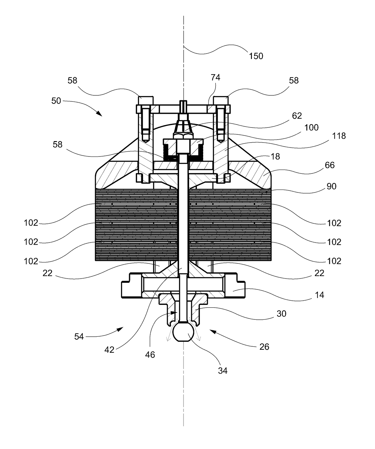
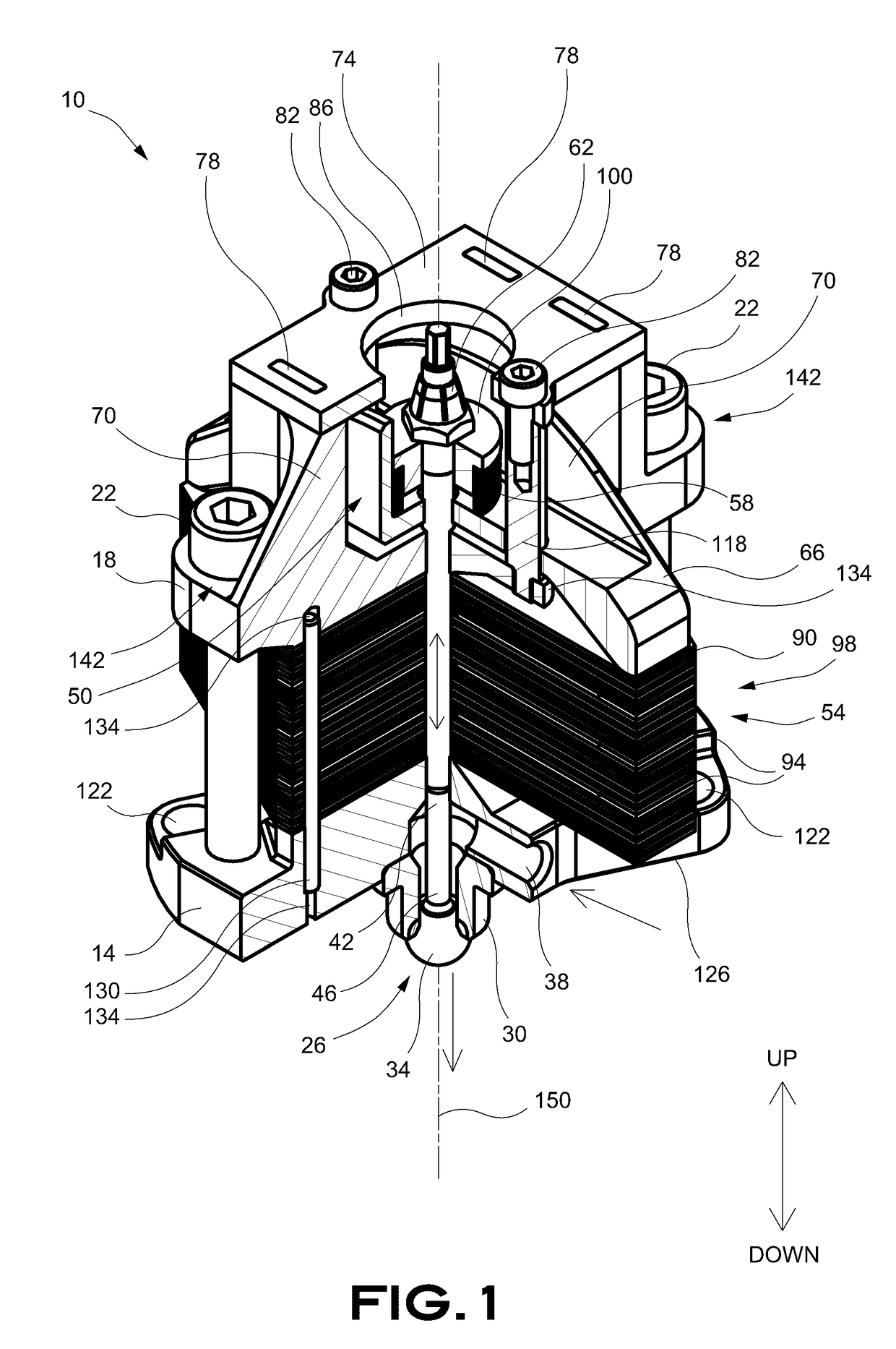
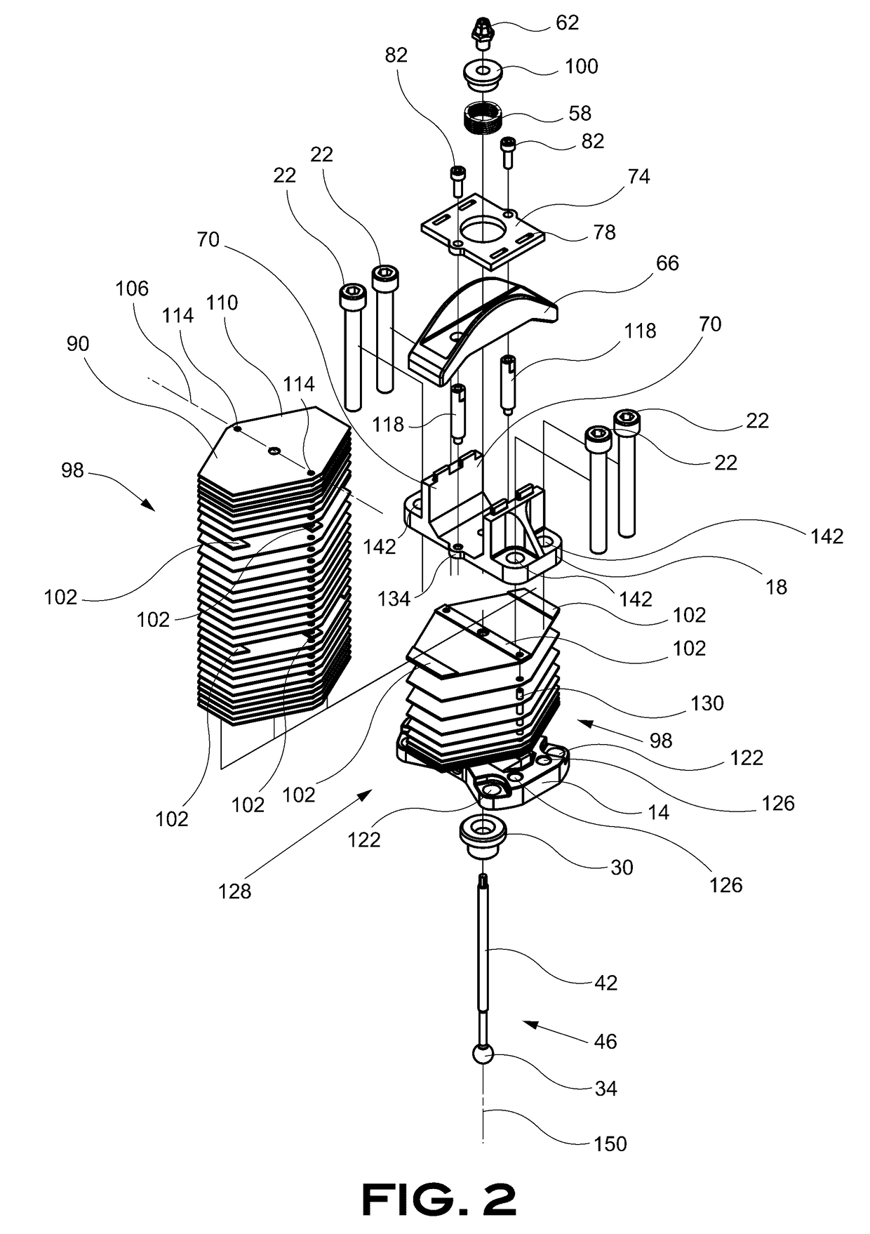
The present invention provides a thermostatic steam trap with improved features and functionality. The steam trap includes a lower casing, an upper casing, and a mechanism that selectively closes the valve as a result of an increasing temperature of the steam trap. The steam trap valve includes a spring mechanism and a strip mechanism that work together to transfer force to close the valve. The steam trap also includes bimetallic plates, a spring mechanism, a bridge portion, and a spring mechanism with a bushing to limit the travel of the stem member against the bimetallic spring. The invention provides a smaller size, symmetrical steam trap, double trapezoidal bimetallic plates, and various combinations and subcombinations of the aforementioned features.

Problems solved by technology

The steam trap assembly has a significant size and is generally heavy.

Method used


Image

  • Thermostatic steam trap
  • Thermostatic steam trap
  • Thermostatic steam trap

Examples


Embodiment Construction

[0028]As a preliminary matter, it will readily be understood by one having ordinary skill in the relevant art (“Ordinary Artisan”) that the invention has broad utility and application. Furthermore, any embodiment discussed and identified as being “preferred” is considered to be part of a best mode contemplated for carrying out the invention. Other embodiments also may be discussed for additional illustrative purposes in providing a full and enabling disclosure of the invention. Furthermore, an embodiment of the invention may incorporate only one or a plurality of the aspects of the invention disclosed herein; only one or a plurality of the features disclosed herein; or combination thereof. As such, many embodiments are implicitly disclosed herein and fall within the scope of what is regarded as the invention.

[0029]Accordingly, while the invention is described herein in detail in relation to one or more embodiments, it is to be understood that this disclosure is illustrative and exem...


PUM


Abstract

A thermostatic steam trap includes a lower casing; an upper casing secured with the lower casing; and a mechanism that is operatively secured with the lower casing and the upper casing and that includes a stack of bimetallic strips. The stack of bimetallic strips includes two opposed cantilevered portions separated by a neutral flexion axis thereof. A stem member slidably extends through the stack of bimetallic strips and the lower casing, and a valve portion includes a valve member that is operatively secured to a first end of the stem member and that selectively closes the valve portion with movement of the cantilevered portions of the stack of bimetallic strips.

Description

COPYRIGHT STATEMENT[0001]All of the material in this patent document is subject to copyright protection under the copyright laws of the United States and other countries. The copyright owner has no objection to the facsimile reproduction by anyone of the patent document or the patent disclosure, as it appears in official governmental records but, otherwise, all other copyright rights whatsoever are reserved.BACKGROUND OF THE INVENTION[0002]The present invention generally relates to apparatus, methods, and systems for extracting condensate from a pressurized system. More particularly, preferred embodiments of the present invention relate to a reduced-size symmetrical steam trap that can trap steam and release condensate depending on pressure and temperature.[0003]Steam traps are known and used in industry to trap steam in pressurized systems. A steam trap is operatively connected in-line to a pressurized system and close when a predetermined temperature is reached. A spring-loaded me...

Claims


Application Information

Patent Timeline
Patent Type & Authority Applications(United States)
IPC IPC(8): F16T1/08
CPCF16T1/08F16T1/38F16T1/383F16T1/02G05D23/00
Inventor WINGERATH, CHRISTIAN MATTHIAS
Owner VELAN INC
Learn More