Image display apparatus, image display method, and system

Active Publication Date: 2018-05-31
CANON KK
View PDF7 Cites 1 Cited by
  • Summary
  • Abstract
  • Description
  • Claims
  • Application Information

AI Technical Summary

Benefits of technology

[0011]The present invention was conceived in view of these kinds of problems, and provides a technique for reducing an amount of information transmitted from a he

Problems solved by technology

One of the most important problems in an AR technique is how to accurately perform alignment between a physical space and a virtual space in real time, and many efforts have been made thus far.
The problem of alignment in AR is the problem of obtaining the position and orientation of an image capturing apparatus in a scene (in other words, a reference coordinate system defined in the scene), when using a video see-through method.
In the case of using an optical see-through method, it is the problem of obtaining

Method used


Image

  • Image display apparatus, image display method, and system
  • Image display apparatus, image display method, and system
  • Image display apparatus, image display method, and system

Examples


first embodiment

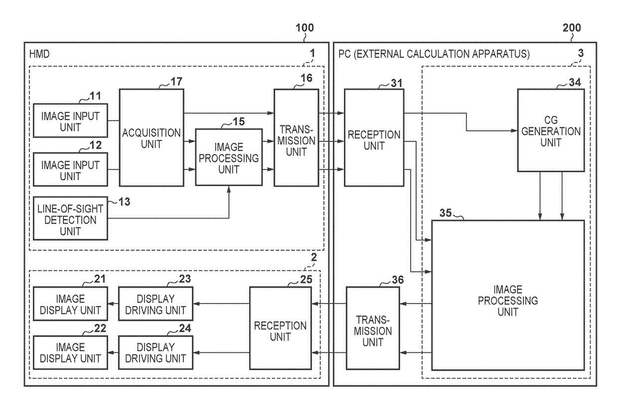
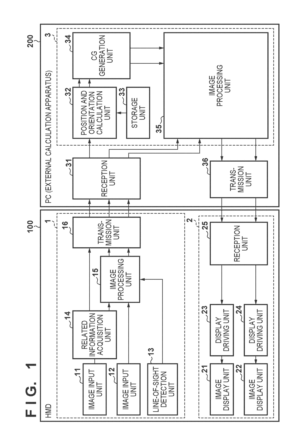
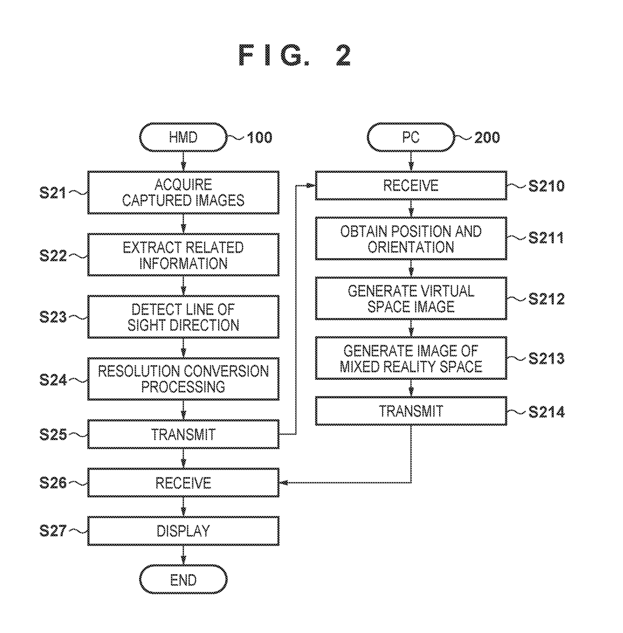
[0023]Firstly, the block diagram of FIG. 1 is used to give an explanation regarding an example of a functional configuration of a system according to the present embodiment. As illustrated in FIG. 1, the system according to the present embodiment has an HMD 100 as a video see-through type head-mounted display, and a PC (external calculation apparatus) 200 as an image processing apparatus for providing the HMD 100 with an image of a mixed reality space achieved by blending a virtual space and a physical space.

[0024]Firstly, explanation is given for the HMD 100. The HMD 100 has an image capturing unit 1 for capturing a physical space that includes an index and transmitting a captured image and information corresponding to the index in the captured image to the PC 200, and a display unit 2 for displaying an image of the mixed reality space transmitted from the PC 200. Firstly, explanation is given for the image capturing unit 1.

[0025]An image input unit 11 has a lens and an image senso...

second embodiment

[0064]In each embodiment or variation below, including the present embodiment, explanation is predominantly given for differences with the first embodiment, and the embodiment or variation is configured to be the same as the first embodiment unless particular mention otherwise is made below. The block diagram of FIG. 4 is used to give an explanation regarding an example of a configuration of a system according to the present embodiment. In FIG. 4, the same reference numerals are added to functional units that are the same as the functional units illustrated in FIG. 1, and explanation for these functional units is omitted. The configuration illustrated in FIG. 4 provides an acquisition unit 17 in place of the related information acquisition unit 14 in the configuration illustrated in FIG. 1, and omits the position and orientation calculation unit 32 and the storage unit 33.

[0065]Similarly to the position and orientation calculation unit 32, the acquisition unit 17 obtains the positio...

third embodiment

[0078]In the first and second embodiments, a gaze position on a captured image was based on a user's line of sight direction that is detected by the line-of-sight detection unit 13. However, determination of a gaze position is not limited to being based on a detection result by the line-of-sight detection unit 13. For example, a defined position on a captured image (for example, a center position of the captured image) may be set in advance as a gaze position. In such a case, the line-of-sight detection unit 13 may be omitted.


PUM


Abstract

Information representing a position and orientation of a captured image or information for deriving the position and orientation is acquired from the captured image as extraction information, and a reduced-information-amount image is generated by reducing an amount of information in the captured image in accordance with a distance from a position that a user is gazing at in the captured image. The reduced-information-amount image and the extraction information are outputted to an external device, and a composite image that has been generated based on the reduced-information-amount image and an image of a virtual space generated by the external device based on the extraction information is received.

Description

BACKGROUND OF THE INVENTIONField of the Invention[0001]The present invention relates to a technique of presenting an image of a mixed reality space.Description of the Related Art[0002]In recent years, mixed reality (MR) techniques in which a presentation is made after blending a physical space and a virtual space without a sense of unnaturalness is being actively researched. In MR techniques, in particular an augmented reality (also referred to as AR) technique for making a presentation after overlapping a virtual space on a physical space has been collecting attention.[0003]AR image presentation is realized by a video see-through method mainly, or by an optical see-through method. In the case of a video see-through method, an image resulting from overlapping an image of a virtual space generated in accordance with a position and orientation of an image capturing apparatus, which is a video camera or the like, on an image of a physical space captured by the image capturing apparatus...

Claims


Application Information

Patent Timeline
IPC IPC(8): G06T19/00G06F3/01G06T7/73G02B27/01
CPCG06T19/006G06F3/013G06T7/73G02B27/0172G02B2027/0138G02B2027/014G06F3/011G06T2207/30204
Inventor INOGUCHI, KAZUTAKAHAMAGUCHI, ATSUSHI
Owner CANON KK
Why Eureka
Try Eureka