Easyly deployable phased antenna for a spacecraft and system of such antennas

a phased antenna and spacecraft technology, applied in the direction of antennas, antenna details, antenna adaptation in movable bodies, etc., can solve the problems of large antenna, need for additional guiding structures and a broad transverse plane, and antenna cannot be placed and deployed on a nanosatelli

Active Publication Date: 2018-05-31
VILNIUS UNIV
View PDF1 Cites 8 Cited by
  • Summary
  • Abstract
  • Description
  • Claims
  • Application Information

AI Technical Summary

Problems solved by technology

The zone can contain a large multitude of devices and the signals from them will overlap in time and interfere with each other.
However, formation of directional and steerable radio beam in VHF and UHF bands requires a large antenna, many times exceeding the standard nanosatellite dimensions.
The major disadvantage of this antenna design is th

Method used


Image

  • Easyly deployable phased antenna for a spacecraft and system of such antennas
  • Easyly deployable phased antenna for a spacecraft and system of such antennas
  • Easyly deployable phased antenna for a spacecraft and system of such antennas

Examples


Embodiment Construction

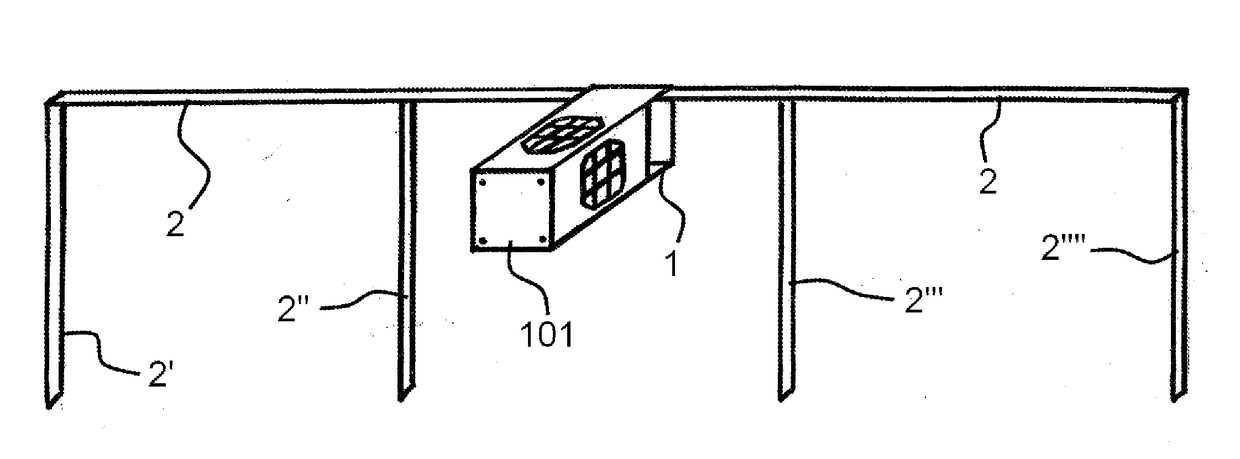
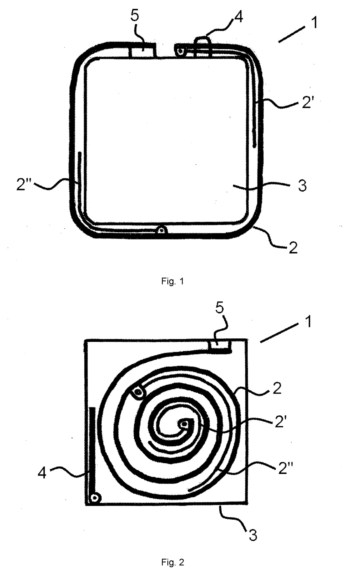
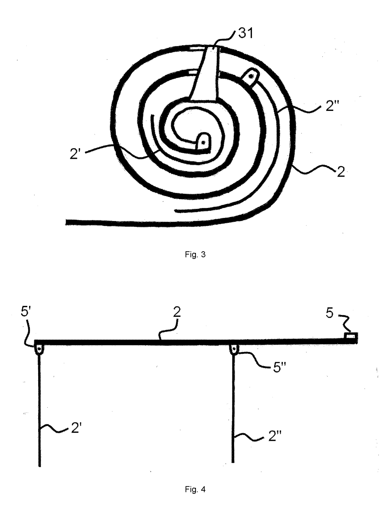
[0014]FIG. 1 and FIG. 2 presents methods of attachment of strip elements (2, 2′, 2″) of a phased array antenna (1) as designed for nanosatellites to the antenna (1) mount in the satellite chamber (3), but not limited to winding of the antenna (1) strip elements (2, 2′, 2″) around the said chamber (3), rolling of the antenna strip members (2, 2′, 2″) into a roll for placement inside the said chamber (3), and folding of the antenna strip elements (2, 2′, 2″) for placement inside chamber (3). In all cases, one end of the antenna transverse strip member (2) is fixed to the mount in the nanosatellite chamber (3) by a fixing accessory (5) and the other end is free.

[0015]The antenna (1) strip members (2, 2′, 2″) are securely held in a collapsed state occupying the least space volume and the monopole electrical vibrators (2′, 2″) and the transverse strip member (2) make an angle close to 0° at the line of attachment until the satellite reaches the intended orbit. Upon reaching the deploymen...


PUM


Abstract

An antenna is made from strips of a shape-memory alloy or other resilient material acting as a spring with attached branches that constitute individual monopole antennas. In the folded state, the antenna looks like a strip roll and can be placed on a satellite. When in orbit, the antenna unfolds after the roll retention mechanism is released and orderly unfolds unrolling from a support frame or otherwise extends. The proposed design of monopole branches utilizes conductors of minimum length and achieves maximum directivity. Each monopole branch is connected to the signal receiver/transmitter by signal conduit elements. A system may include at least two such unfolding antennas thus achieving even greater operational effectiveness in regard to signal steerability, interference suppression and reduced moment of the satellite inertia. To prevent problems, additional measures are used that prevent unwinding of inner layers of the roll before the outer layer is extended.

Description

FIELD OF THE INVENTION[0001]This invention relates to deployable spacecraft antennas, and more specifically with phased array deployable antennas and their systems, which can be packed into a small volume of nanosatellites.BACKGROUND OF THE INVENTION[0002]Recently, miniaturized satellites, such as Cube-sat nanosatellites, are increasingly widely used. The dimensions of a single nanosatellite module according to this standard are 10 cm×10 cm×10 cm. Larger satellites can also be built out of these modules. A single module normally consists of various structural elements, such as reflectors, transceivers, antennas, sensors, etc. In spite of the small dimensions, the nanosatellites are used for various tasks. Some of them require directional and steerable beam in VHF and UHF bands, as is the case when tracking ships (AIS systems), aircraft (ADS-B), and radio beacons (Argos) from space. As a rule, nanosatellites are equipped with deployable single-strip monopoly antennas (Encinas Plaza, ...

Claims


Application Information

Patent Timeline
IPC IPC(8): H01Q1/12H01Q21/12H01Q1/28H01Q19/04H01Q3/26
CPCH01Q1/1235H01Q1/288H01Q19/04H01Q21/12H01Q3/26
Inventor RUDYS, SAULIUSBANYS, JURAS
Owner VILNIUS UNIV
Why Eureka
Try Eureka