Optical tap module

Inactive Publication Date: 2007-08-16
GOFOTON HLDG
View PDF5 Cites 6 Cited by
  • Summary
  • Abstract
  • Description
  • Claims
  • Application Information

AI Technical Summary

Benefits of technology

[0059] According to the configuration of the optical tap module of the invention, even when backward light from the second optical fiber is incident, light is not irradiated onto the surfaces of the photodiode and the chip mounting support, and thus reflected/scattered light from incident light is prevented. Therefore, the directivity of the tap module can be improved. Further, the invention can be applied to an optical tap module for an optical fiber

Problems solved by technology

If a normal optical tap is used at the previous stage of the optical amplifier, since ASE is incident from an output-side of the optical tap, a background level of the photodiode output rises, and thus it is difficult to accurately measure the intensity of incident light.
However, in the related art, there are the following problems.
The directivity of the optical tap module required for the optical fiber amplifier is about 30 dB, and thus insufficient directivity is obtained in the configuration according to the related art.
When a light-shielding film is provided in the chip

Method used


Image

  • Optical tap module
  • Optical tap module
  • Optical tap module

Examples


first example

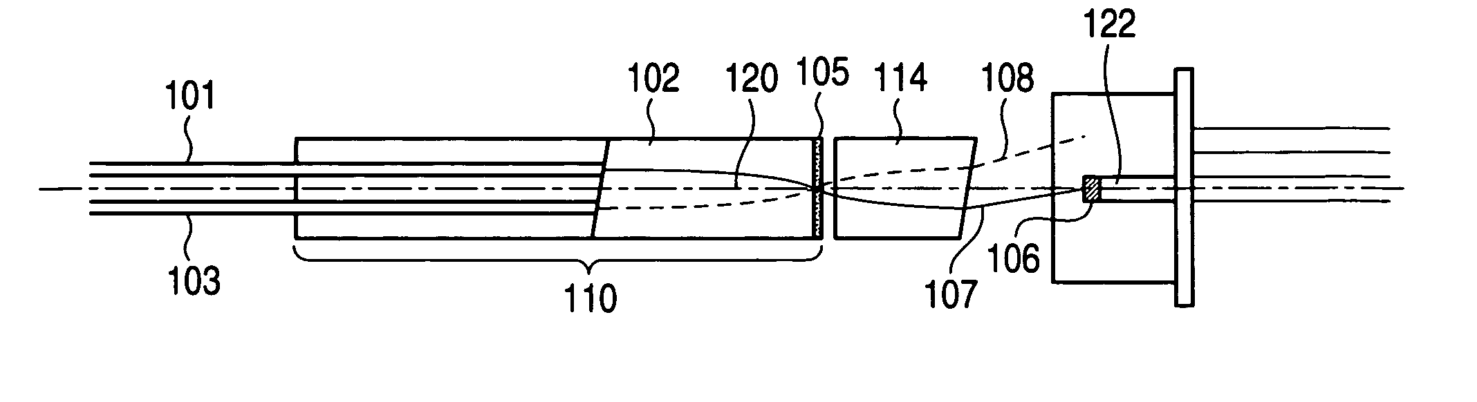
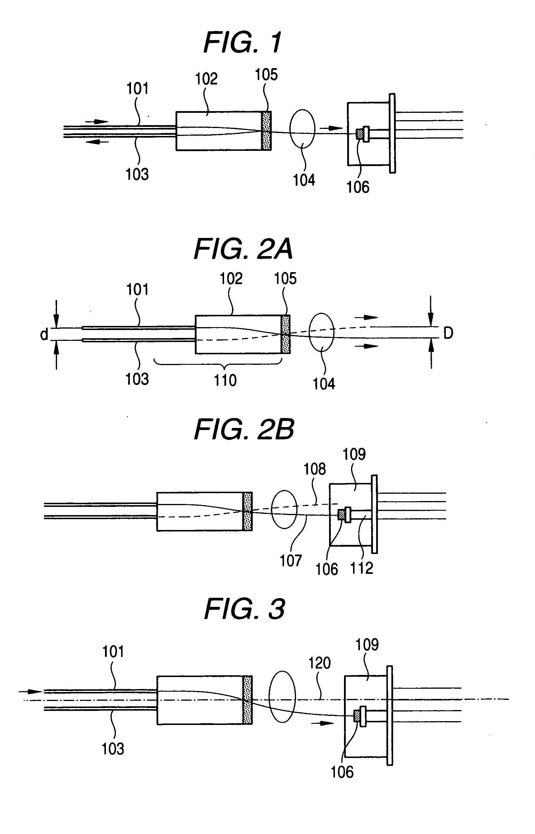
[0087]FIG. 9 shows a unidirectional tap module according to a first example of the invention. Light emitted from an optical fiber 1 for incident light is incident on a gradient index rod lens 2. The gradient index rod lens 2 is manufactured to have 0.25 pitch (meandering cycle) with respect to a used wavelength band, and is designed such that incident light from the optical fiber is emitted as parallel light. Parallel light emitted from the rod lens 2 is incident on an optical filter (tap filter) which is directly formed on an end surface of the rod lens as a thin-layered optical functional element. The filter 5 is designed to have reflectance of 95% and transmittance of 5%.

[0088] Light reflected by the filter 5 is converged by the rod lens 2 again and is incident on an output optical fiber 3. On the other hand, transmitted light from the filter 5 is converged by a second gradient index rod lens (focusing lens) 4 of 0.12 pitch, and is incident on a photodiode 6. Further, the emitti...

second example

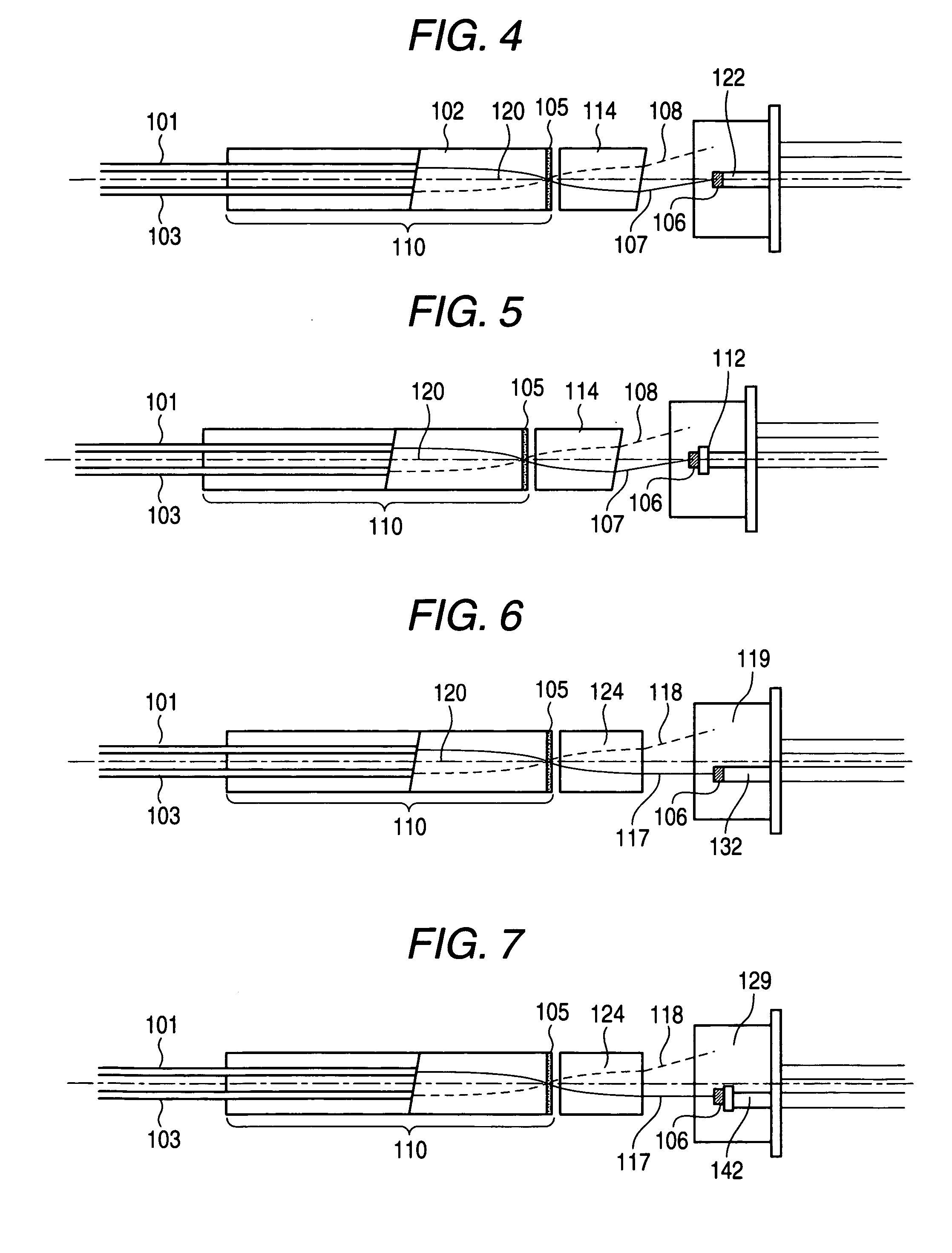
[0094]FIG. 11 shows of a unidirectional tap module according to a second example of the invention. The optical fibers 1 and 3, the two-core capillary 7 supporting the optical fibers 1 and 3, the rod lenses 2 and 4 are the same as those in the first example. However, the tap filter 15 was designed to have reflectance of 99% and transmittance of 1%. As a pin 22, on which the chip of a package 19 was mounted, a straight pin, not a normal nail pin, was used. The diameter of the pin 22 was 0.45 mm. The chip of the photodiode 6 had the diagonal size of 240 μm, like the first example.

[0095] The chip was mounted on the end surface of the pin 22. In this example, as shown in FIG. 11, the entire package 9 of the photodiode was obliquely fixed by 8° so as to reduce reflection feedback light. If the surface of the pin is processed obliquely, and the chip is mounted, the package does not need to be inclined.

[0096] When the directivity of the module was measured, the same result as the first ex...


PUM


Abstract

In an optical tap module, a first lens, a focusing lens, and a photodiode are arranged such that a center axis of a cylindrical case housing the first lens, the focusing lens, and the photodiode is substantially located on the same line. When light propagates through a second optical fiber and is emitted from an end surface facing the first lens so as to be incident on an optical filter, and light transmitted the optical filter is converged by the focusing lens, the photodiode and a chip mounting support are arranged such that a focal point of light is located spatially distant from the surfaces of the photodiode and the chip mounting support.

Description

BACKGROUND OF THE INVENTION [0001] 1. Field of the Invention [0002] The present invention relates to an optical tap module which is used to monitor an optical signal in an optical fiber transmission line in a field of an optical communication or optical measurement. [0003] 2. Related Art [0004] In an optical communication system or optical measurement system, in view of monitoring the system, the detection of presence / absence of signal light propagating through a transmission line, such as an optical fiber or the like, or its intensity is required. Further, when a device having an action, such as amplification or modulation, on signal light is used, signal light is monitored and the device gets the feedback action result. Such a monitoring function is basically implemented by branching off some of signal light from the transmission line through a branching unit having a predetermined branching ratio and by causing an optical detector to detect branched signal light. [0005] As a unit...

Claims


Application Information

Patent Timeline
IPC IPC(8): G02B6/26G02B6/32
CPCG02B6/2937G02B6/2938G02B6/4215G02B6/4206G02B6/29385
Inventor NAGATA, HISAOHASHIZUME, HIDEKISATO, AKIMITSU
Owner GOFOTON HLDG
Why Eureka
Try Eureka