Cleaning method and film deposition apparatus

a cleaning method and film deposition technology, applied in the direction of chemical vapor deposition coating, vacuum evaporation coating, coating, etc., can solve the problems of increasing the cleaning time needed, ejecting the majority of cleaning gas, and high flow rate of cleaning gas supplied from the nozzl

Active Publication Date: 2018-06-07
TOKYO ELECTRON LTD
View PDF4 Cites 6 Cited by
  • Summary
  • Abstract
  • Description
  • Claims
  • Application Information

AI Technical Summary

Benefits of technology

[0048]Below, a cleaning method according to an embodiment is described. The cleaning method of the embodiment can reduce the cleaning time and can uniformly clean the rotary table 2.

Problems solved by technology

With the related-art method, however, because the gap between a nozzle for supplying the cleaning gas and the rotary table is narrow, the flow rate of the cleaning gas supplied from the nozzle becomes high and most of the cleaning gas is ejected before the film deposited on the upper surface of the rotary table is removed.
This in turn increases the cleaning time necessary to remove the film deposited on the upper surface of the rotary table, and causes the time necessary to remove the film to vary depending on surfaces of the rotary table.

Method used


Image

  • Cleaning method and film deposition apparatus
  • Cleaning method and film deposition apparatus
  • Cleaning method and film deposition apparatus

Examples


Embodiment Construction

[0015]Embodiments of the present invention are described below with reference to the accompanying drawings. Throughout the specification and the drawings, the same reference number is assigned to substantially the same components, and repeated descriptions of those components are omitted.

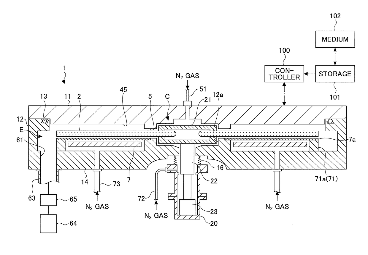
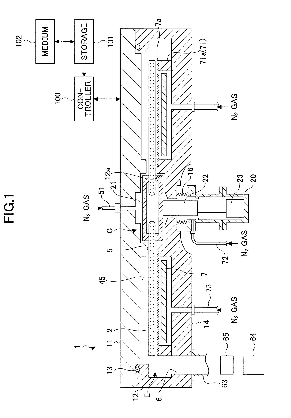
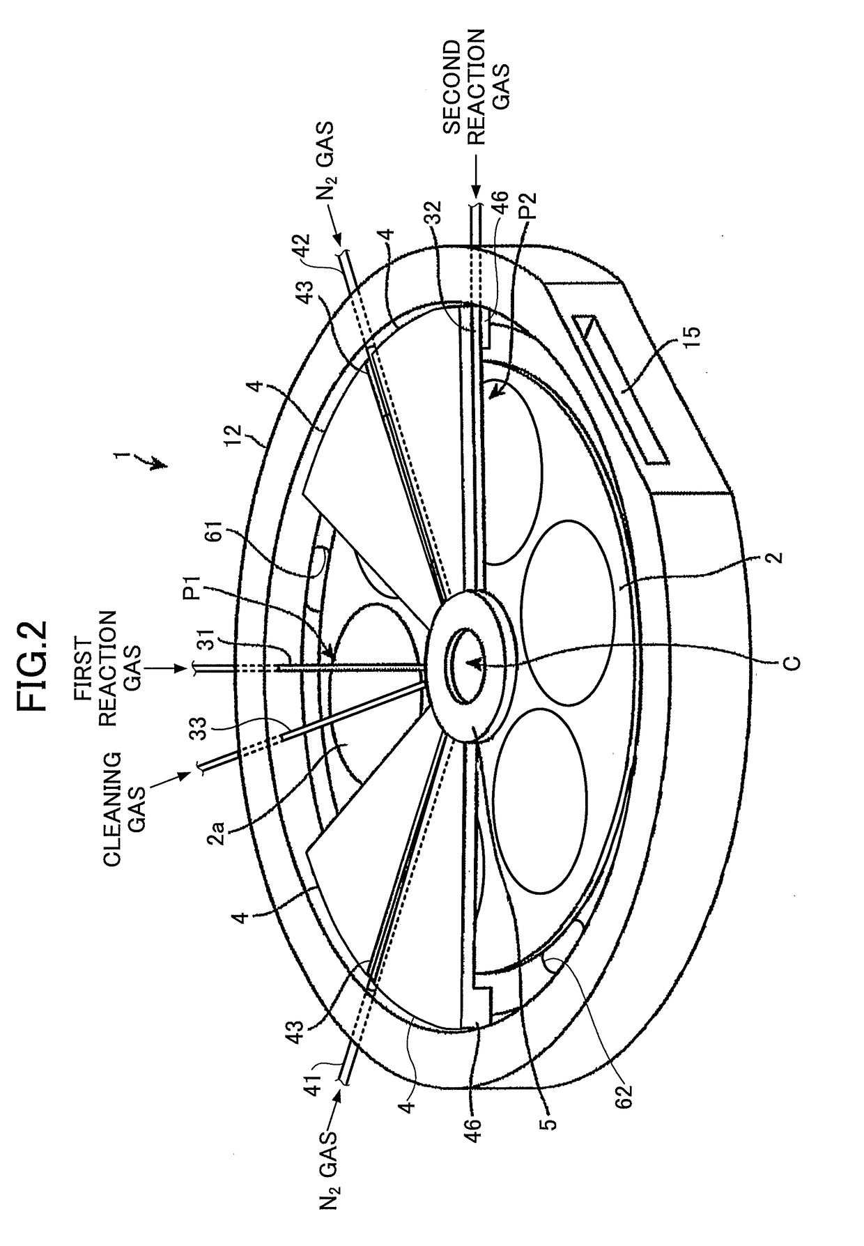
[0016]An example of a film deposition apparatus that can perform cleaning methods according to embodiments of the present invention is described. FIG. 1 is a cross-sectional view of a film deposition apparatus according to an embodiment. FIG. 2 is a perspective view of an internal configuration of a vacuum chamber of the film deposition apparatus of FIG. 1. FIG. 3 is a plan view of the internal configuration of the vacuum chamber of the film deposition apparatus of FIG. 1. In FIGS. 2 and 3, a top plate 11 is omitted for illustration purposes.

[0017]As illustrated by FIGS. 1 through 3, the film deposition apparatus may include a vacuum chamber 1 having a substantially circular planar shape, and a rota...


PUM

PropertyMeasurementUnit
diameteraaaaaaaaaa
flow rateaaaaaaaaaa
thicknessaaaaaaaaaa

Abstract

A method performed by a film deposition apparatus including a process chamber and a rotary table that is disposed in the process chamber and includes a substrate-mounting surface on which a substrate is placeable. The method includes a first cleaning process of supplying a cleaning gas from above the substrate-mounting surface of the rotary table while rotating the rotary table in a first cleaning position, and a second cleaning process of supplying the cleaning gas from above the substrate-mounting surface of the rotary table while rotating the rotary table in a second cleaning position that is lower than the first cleaning position.

Description

CROSS-REFERENCE TO RELATED APPLICATION[0001]The present application is based upon and claims the benefit of priority of Japanese Patent Application No. 2016-237074, filed on Dec. 6, 2016, the entire contents of which are incorporated herein by reference.BACKGROUND OF THE INVENTION1. Field of the Invention[0002]An aspect of this disclosure relates to a cleaning method and a film deposition apparatus.2. Description of the Related Art[0003]In a film deposition apparatus used for manufacturing semiconductor devices, a film is deposited not only on the upper surface of a substrate but also on the upper surface, the side surface, and the lower surface of a rotary table on which the substrate is placed. When the film deposited on the upper surface, the side surface, and the lower surface of the rotary table becomes thick, the film flakes off and forms particles. For this reason, a cleaning gas is routinely supplied into a process chamber to remove the film deposited on the upper surface, t...

Claims


Application Information

Patent Timeline
Patent Type & Authority Applications(United States)
IPC IPC(8): C23C16/44C23C16/458C23C14/50C23C22/34
CPCC23C16/4405C23C16/458C23C14/505C23C22/34C23C16/401C23C16/45548C23C16/4584H01L21/02046H01L21/67028
Inventor TAMURA, TATSUYAUMEHARA, TAKAHITO
Owner TOKYO ELECTRON LTD
Why Eureka
Try Eureka