Low temperature CVD chamber cleaning using dilute NF3

a technology of cvd chamber and dilute nf3, which is applied in the field of low temperature cvd chamber cleaning using dilute nf3, can solve problems such as defects in electronic product components, and achieve the effect of reducing the cool down period of susceptors and cleaning at lower plasma energies

Inactive Publication Date: 2005-11-17
AIR PROD & CHEM INC
View PDF17 Cites 13 Cited by
  • Summary
  • Abstract
  • Description
  • Claims
  • Application Information

AI Technical Summary

Benefits of technology

[0015] an ability to reduce the susceptor cool down period after the chamber has been cleaned; and, an ability to clean at lower plasma energies.

Problems solved by technology

Any material, film and the like that builds up on the walls, tool surfaces, susceptors and other equipment is considered a contaminant and may lead to defects in the electronic product component.

Method used


Image

  • Low temperature CVD chamber cleaning using dilute NF3
  • Low temperature CVD chamber cleaning using dilute NF3

Examples


example i

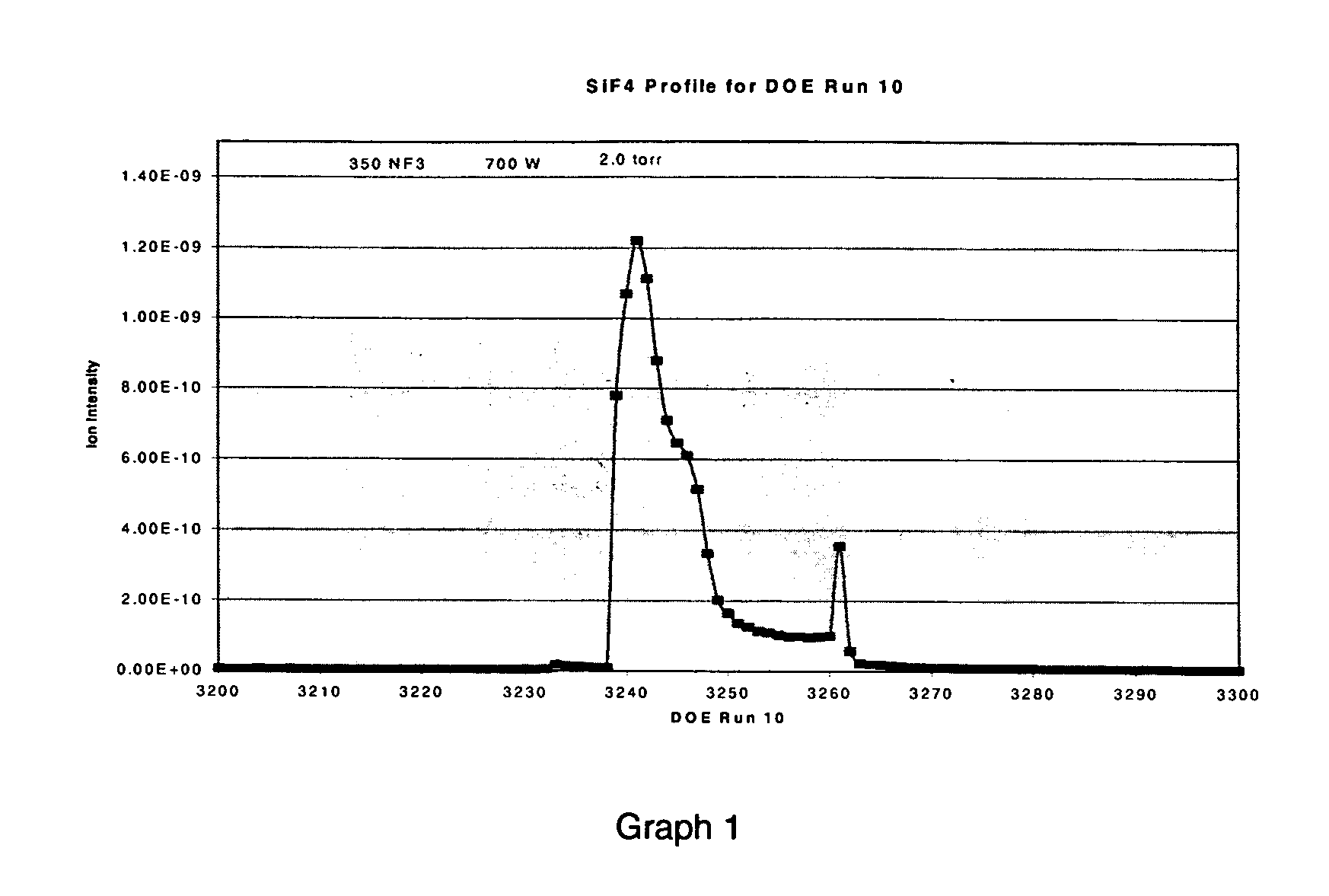
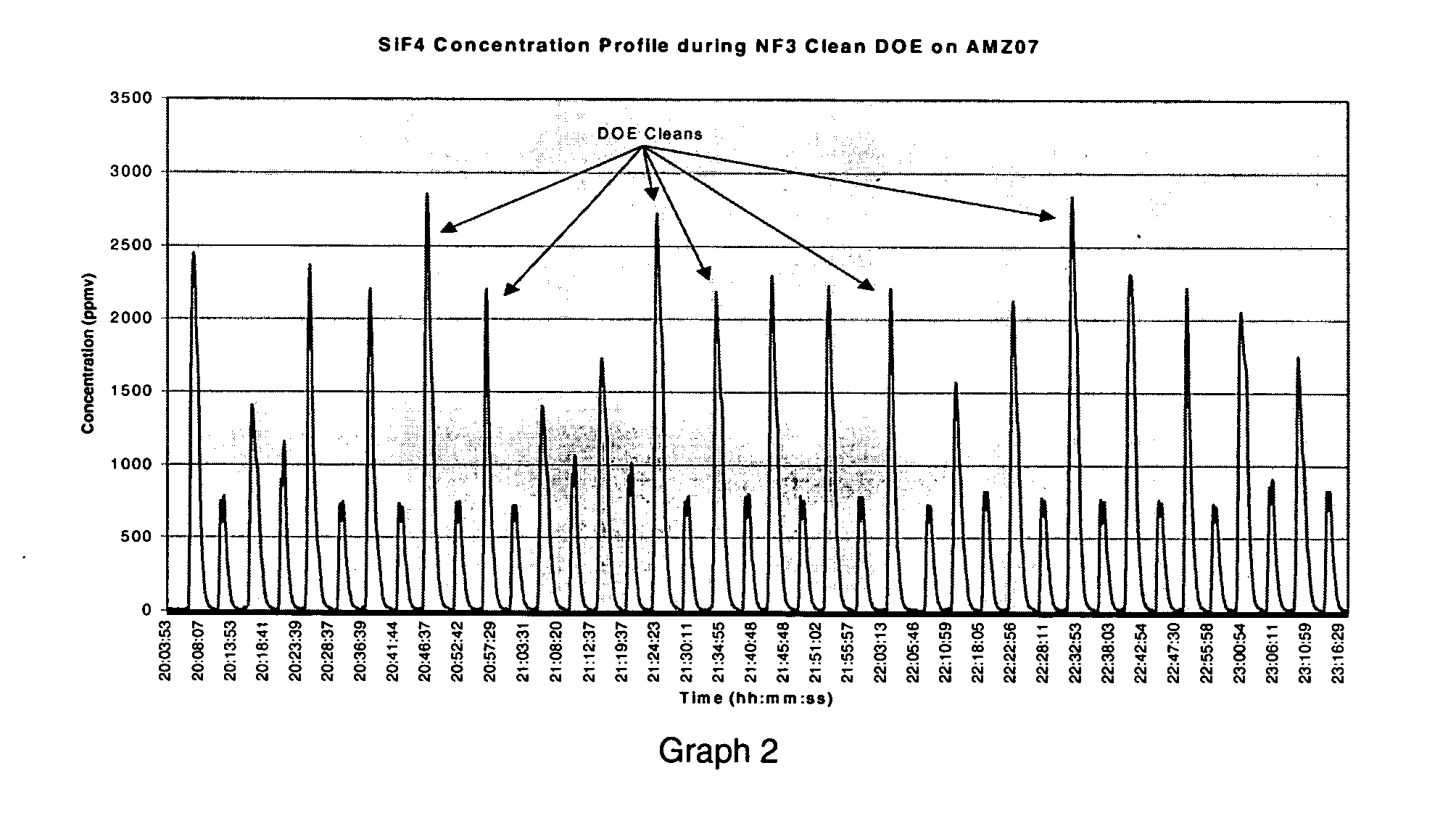
[0030] In this example susceptor temperature rise, clean time and integrated SiF4 emissions associated with the standard clean chemistry are compared to an optimized a dilute NF3 / helium cleaning chemistry. Experimental design methods were used to model responses for susceptor temperature rise, cleaning time to end point and integrated SiF4 emissions as a function of plasma power, pressure and PFC flow rates. The models were created by imputing data into a commercially available statistical software. A central composite response surface model was created. Three center point replicates were run for each model. For each DOE run the chamber clean was timed at 45 sec. The film thickness deposited on the wafer was 3000 Angstroms for each run. Between each DOE run a 30 sec. chamber clean was run using the standard recipe to ensure that residual film was removed prior to the subsequent DOE run.

[0031] Data supporting models were acquired in the following manner. The susceptor temperature wa...

example 2

Comparison Of Model Simulated Conditions For Optimized Dilute NF3 Based Chemistry Relative to Optimized Standard Chemistry

[0041] In this example susceptor temperature rise, clean time and integrated SiF4 emissions associated with the optimized standard clean chemistry are compared to an optimized dilute NF3 cleaning chemistry. Experimental design methods were used to model responses for susceptor temperature rise, cleaning time to end point and integrated SiF4 emissions as a function of plasma power, pressure and PFC flow rates. The models were created by imputing data into a commercially available statistical software. A central composite response surface model was created. Three center point replicates were run for each model. For each DOE run the chamber clean was timed at 45 sec. Between each DOE run a 30 sec. chamber clean was run using the standard recipe to ensure that residual film was removed prior to the subsequent DOE run.

[0042] Data supporting models were acquired in t...


PUM

PropertyMeasurementUnit
susceptor temperatureaaaaaaaaaa
temperaturesaaaaaaaaaa

Abstract

This invention relates to an improvement in in-situ cleaning of deposition byproducts in low temperature Plasma Enhanced Chemical Vapor Deposition (PECVD) chambers and hardware therein where process thermal budgets require minimization of the susceptor temperature rise. In the basic in situ PECVD process, a cleaning gas is introduced to the chamber for a time and temperature sufficient to remove films of the deposition byproducts and then the cleaning gas containing deposition byproducts removed from said PECVD chamber. The improvement for minimizing the susceptor temperature rise in a low temperature PECVD chamber during cleaning comprises:
    • employing a cleaning gas consisting essentially of NF3 for cleaning and diluted with a sufficient amount of helium to carry away the heat developed during cleaning of the Plasma Enhanced Low Temperature Chemical Vapor Deposition chamber. The susceptor is maintained at 150° C. or below.

Description

BACKGROUND OF THE INVENTION [0001] In the electronics industry, various deposition techniques have been developed wherein selected materials are deposited on a target substrate to produce electronic components such as semiconductors. One type of deposition process is chemical vapor deposition (CVD), wherein gaseous reactants are introduced into a heated processing chamber resulting in films being deposited on the desired substrate. One subtype of CVD is referred to a plasma enhanced CVD (PECVD), wherein a plasma is established in the CVD processing chamber. Exposing the reactants to the plasma in the CVD chamber increases their reactivity, thus, less heat is required in the chamber to yield the desired deposition. [0002] Generally, all methods of deposition result in the accumulation of films and particulate materials on surfaces other than the target substrate, that is, the deposition materials also collect on the walls, tool surfaces, susceptors, and on other equipment used in the...

Claims


Application Information

Patent Timeline
Patent Type & Authority Applications(United States)
IPC IPC(8): B08B7/00C23C16/44C23F4/00H01L21/205H01L21/3065
CPCB08B7/00H01J37/32862C23C16/4405B08B7/0035H01L21/205
Inventor RIDGEWAY, ROBERT GORDONJI, BINGMAROULIS, PETER JAMES
Owner AIR PROD & CHEM INC
Why Eureka
Try Eureka