Aircraft seal structure and aircraft

a technology for sealing structures and aircraft, applied in fireproofing, efficient propulsion technologies, machines/engines, etc., can solve the problems of insufficient sealing of the seal contact surface, and achieve the effect of reducing the burden on sealing maintenan

Active Publication Date: 2018-06-07
MITSUBISHI AIRCRAFT
View PDF6 Cites 12 Cited by
  • Summary
  • Abstract
  • Description
  • Claims
  • Application Information

AI Technical Summary

Benefits of technology

[0028]In one or more embodiments, friction of the second elastic seal is small even if the second elastic seal is in contact with the seal contact surface, in the stationary state and until the second elastic seal is pressed against the seal contact surface due to relative displacement of the first member and the second member. Accordingly, even when the valve seal is ad

Problems solved by technology

The seal contact surface, however, may not be sufficiently secured in som

Method used


Image

  • Aircraft seal structure and aircraft
  • Aircraft seal structure and aircraft
  • Aircraft seal structure and aircraft

Examples


Embodiment Construction

[0040]Embodiments of the present invention are described below with reference to accompanying drawings.

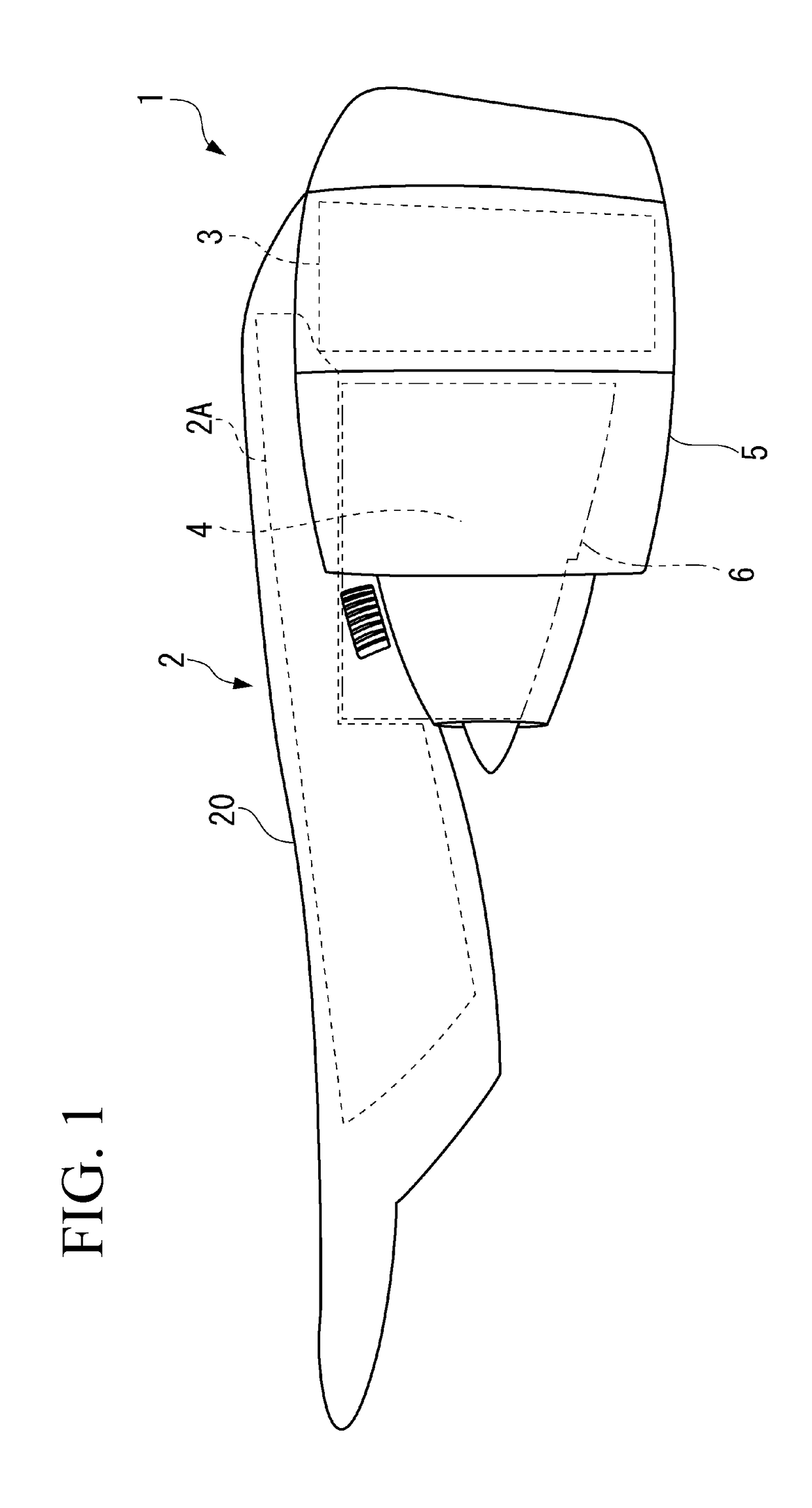
[0041]An engine 1 of an aircraft illustrated in FIG. 1 is supported to an unillustrated main wing by a pylon 2.

[0042]According to one or more embodiments, the engine 1 includes a fan 3, an engine core (compressor and combustion chamber) 4 that is a main body of the engine 1, and a cylindrical engine nacelle 5 that surrounds the fan 3 and the engine core (compressor and combustion chamber) 4.

[0043]The pylon 2 includes a pylon main body 2A as a structure member, and a pylon fairing 20 that covers the pylon main body 2A.

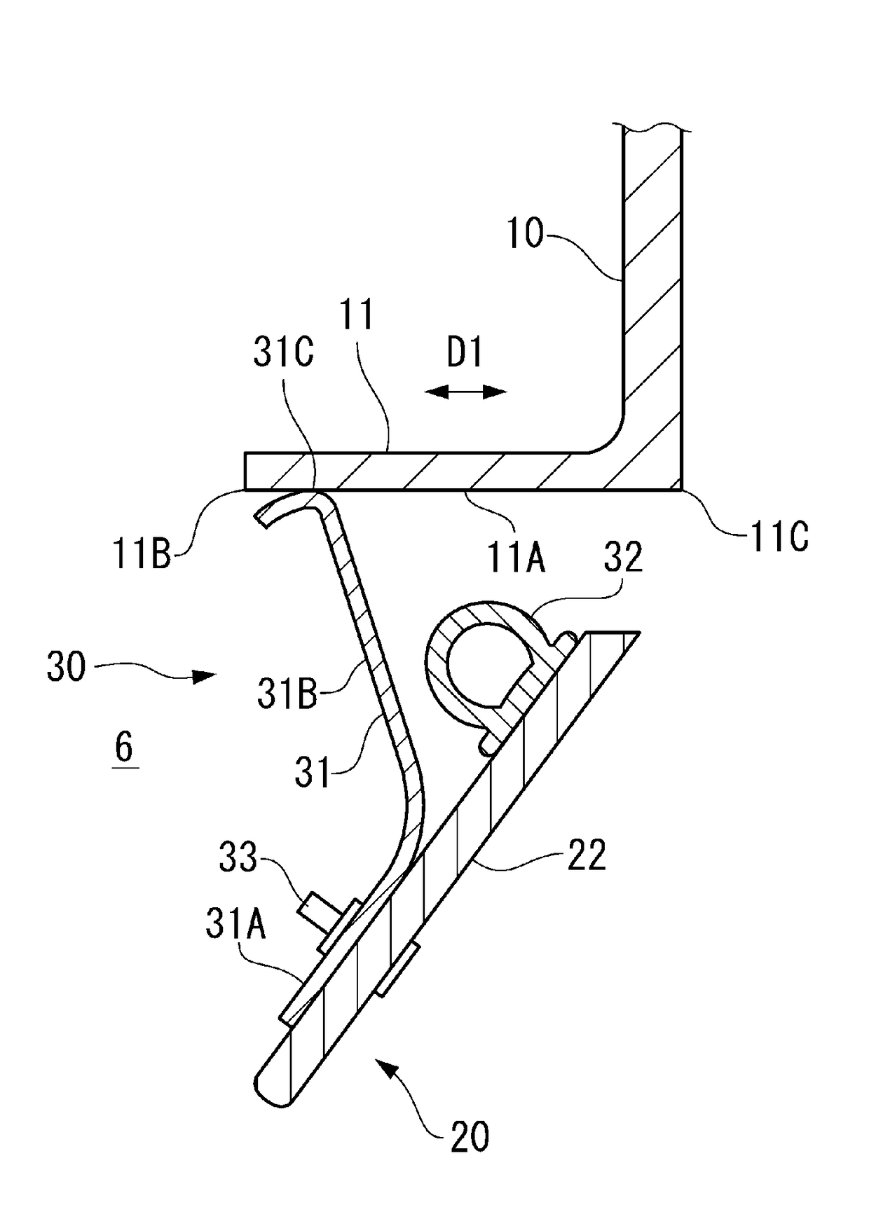
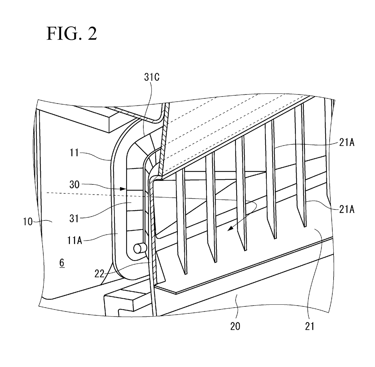
[0044]A fire-prevention region 6 according to one or more embodiments is defined around the engine core (compressor and combustion chamber) 4 for fire occurred from the engine core (compressor and combustion chamber) 4, and it is required to prevent flame from coming out of the fire-prevention region 6. In FIG. 1, an approximate outer shape of the fire-prevention regio...


PUM


Abstract

A seal structure for sealing a gap between a first member and a second member of an aircraft includes: a plate spring-shaped first elastic seal; and a second elastic seal. When the first member and the second member are stationary with respect to each other, the first elastic seal elastically deforms between the first member and the second member to seal the gap, whereas the second elastic seal does not seal the gap. When the first member and the second member move closer to each other and the first elastic seal is elastically deformed, the second elastic seal elastically deforms between the first member and the second member to seal the gap.

Description

BACKGROUND OF THE INVENTIONField of the Invention[0001]The present invention relates to a seal structure for an aircraft and to an aircraft.[0002]The seal structure for the aircraft includes, as one form, a fire seal structure that prevents flame from coming out of a fire-prevention region of the aircraft.Description of the Related Art[0003]A fire-prevention region is designated around an ignition source that may generate flame, such as an engine main body and an auxiliary power unit of an aircraft, and it is required to prevent the flame generated inside the fire-prevention region from coming out of the fire-prevention region.[0004]For example, the fire-prevention region that confines the flame generated from the engine main body (engine core) is designated inside an engine nacelle.[0005]When the fire occurs from the engine main body, it is necessary to prevent the flame from passing through a gap between the engine nacelle and a pylon to blow off to outside. Accordingly, the gap b...

Claims


Application Information

Patent Timeline
IPC IPC(8): F02C7/25E04B1/94B64D27/26
CPCF02C7/25E04B1/948B64D27/26B64C7/02B64D29/00B64D2045/009B64C7/00B64D45/00Y02T50/40Y02T50/60
Inventor TAKEUCHI, AKIRA
Owner MITSUBISHI AIRCRAFT
Why Eureka
Try Eureka