
Electrode structure and liquid crystal display panel

a liquid crystal display panel and electrode structure technology, applied in static indicating devices, instruments, non-linear optics, etc., can solve the problems of color distortion, adverse effects on the light transmittance of the panel, and decrease in the brightness of the sub-domain, so as to eliminate the phenomenon of color distortion

Active Publication Date: 2018-06-07
SHENZHEN CHINA STAR OPTOELECTRONICS TECH CO LTD
View PDF2 Cites 3 Cited by
  • Summary
  • Abstract
  • Description
  • Claims
  • Application Information

AI Technical Summary

Benefits of technology

The present invention provides an electrode structure for a liquid crystal display panel that optimizes the electric field distribution and orientation of liquid crystal, resulting in improved display performance and maintained aperture ratio when viewed from a wide angle. This is achieved by arranging the branch electrodes at different positions to form different trunk-branch angles with the corresponding trunk electrode. Overall, this innovation helps to eliminate color distortion and ensure a high-quality display.

Problems solved by technology

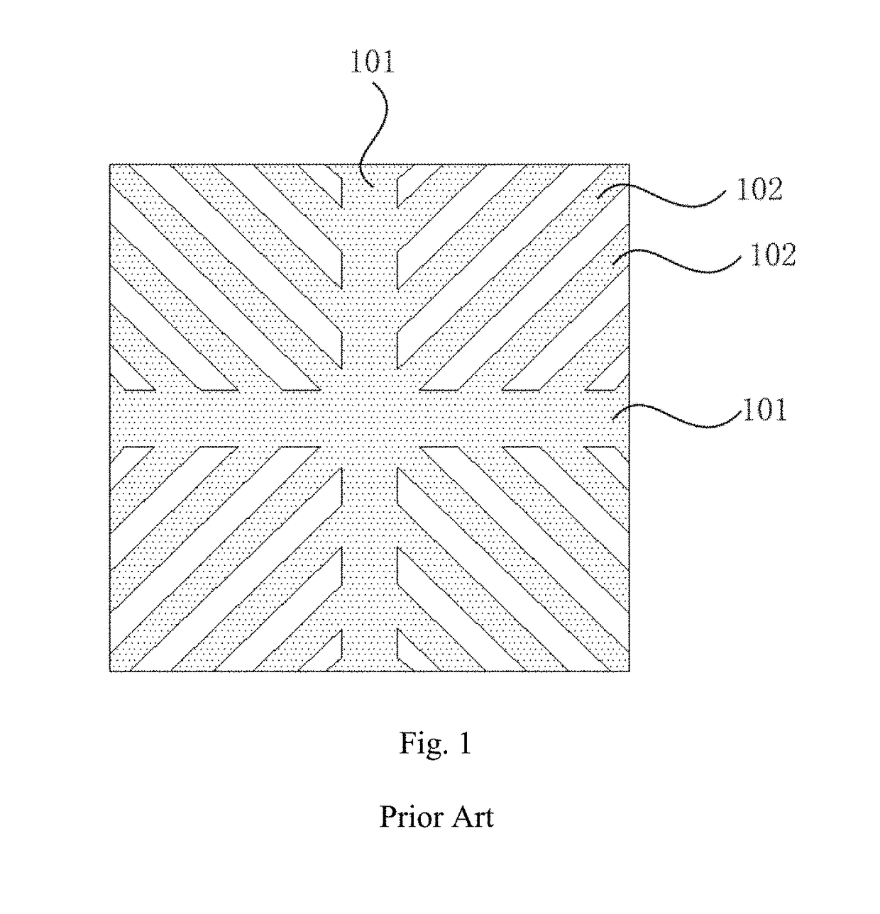
Since liquid crystal has different orientations when a panel is watched under different viewing angles, a color distortion would be resulted in when the panel is watched under a wide viewing angle.
As a result, a brightness of the sub domain would decreases, and a light transmittance of the panel would be adversely affected.

Method used


Image

  • Electrode structure and liquid crystal display panel
  • Electrode structure and liquid crystal display panel
  • Electrode structure and liquid crystal display panel

Examples


embodiment 1

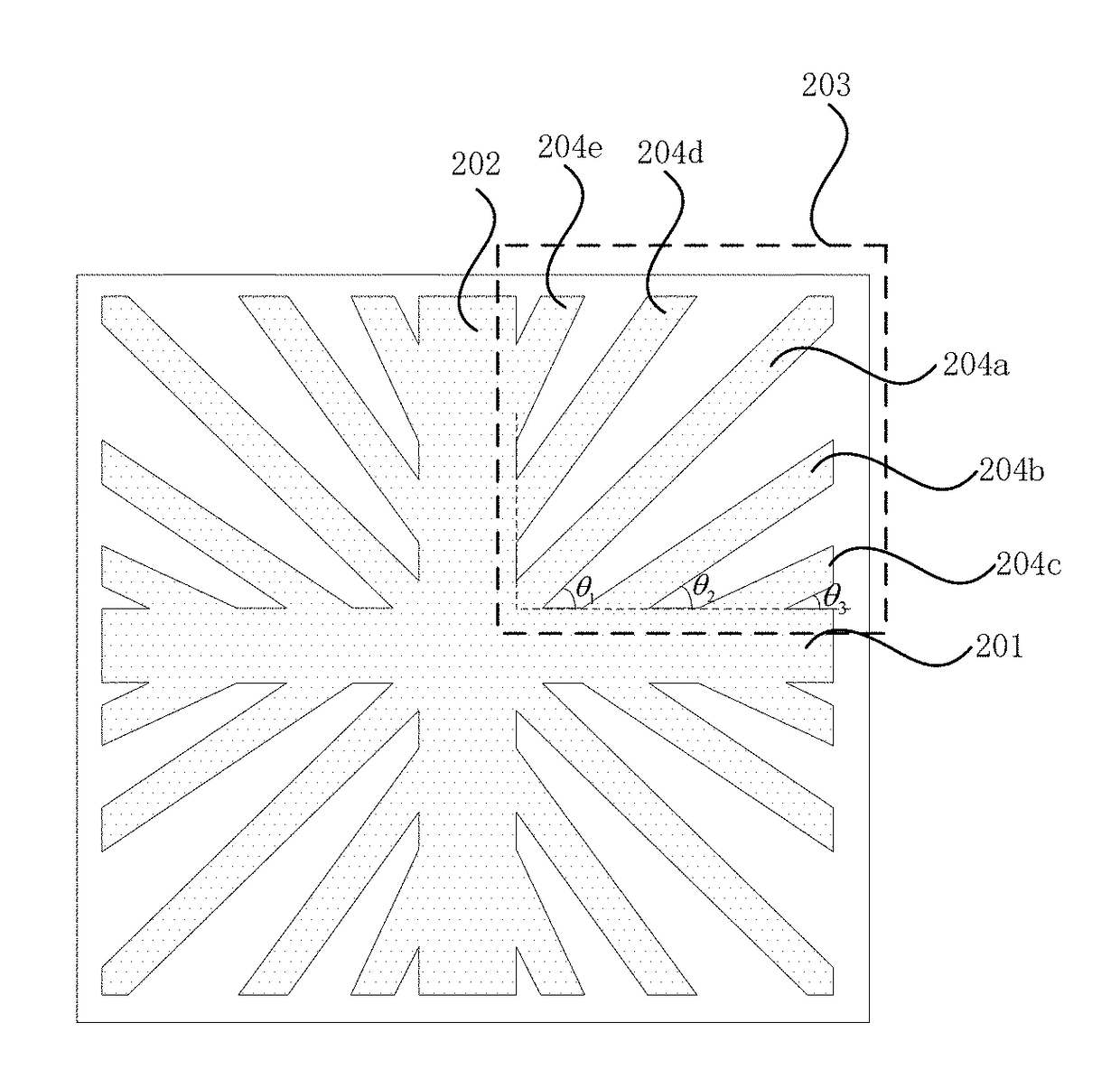
[0033]FIG. 2 schematically shows an electrode structure according to the present embodiment. According to the present embodiment, the electrode structure is a pixel electrode structure. Of course, according to other embodiments of the present disclosure, the electrode structure can also be used in other reasonable electrodes of a liquid crystal display panel, and the present disclosure is not limited by this.

[0034]According to the present embodiment, the electrode structure comprises a first trunk electrode 201, a second trunk electrode 202, and a plurality of branch electrodes. The first trunk electrode 201 and the second trunk electrode 202 intersect with each other and are perpendicular to each other so as to form four domains. An intersecting point of the first trunk electrode 201 and the second trunk electrode 202 is a trunk electrode intersecting point. According to the present embodiment, a width of the first trunk electrode 201 is equal to a width of the second trunk electro...

embodiment 2

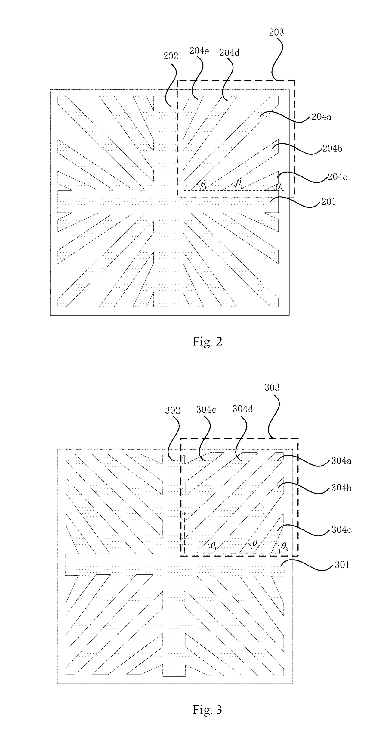
[0045]FIG. 3 schematically shows an electrode structure according to the present embodiment. According to the present embodiment, the electrode structure is a pixel electrode structure. Of course, according to other embodiments of the present disclosure, the electrode structure can also be used in other reasonable electrodes of a liquid crystal display panel, and the present disclosure is not limited by this.

[0046]Similar to the electrode structure as shown in FIG. 2, according to the present embodiment, the pixel electrode structure comprises a first trunk electrode 301, a second trunk electrode 302, and a plurality of branch electrodes. The first trunk electrode 301 and the second trunk electrode 302 intersect with each other and are perpendicular to each other so as to form four domains. An intersecting point of the first trunk electrode 301 and the second trunk electrode 302 is a trunk electrode intersecting point. According to the present embodiment, the branch electrodes in th...


PUM


Abstract

An electrode structure and a liquid crystal display panel are disclosed. The electrode structure comprises a first trunk electrode and a second trunk electrode, the first trunk electrode and the second trunk electrode intersecting with each other to form a trunk electrode intersecting point; and a plurality of branch electrodes, the branch electrodes being spaced from one another, and one end of each branch electrode being connected with at least one of the first trunk electrode and the second trunk electrode and forming a trunk-branch angle with a corresponding trunk electrode. The trunk-branch angles of the branch electrodes decrease gradually or increase gradually along a direction from the trunk electrode intersecting point to far therefrom. An electric field distribution in the electrode structure can be optimized, and an orientation of liquid crystal can be optimized accordingly. Therefore, a display performance of the liquid crystal display panel under a wide viewing angle can be improved, and an aperture ratio thereof can be maintained.

Description

CROSS REFERENCE TO RELATED APPLICATIONS[0001]The present application claims the priority of Chinese patent application CN201510663153.9, entitled “Electrode Structure and Liquid Crystal Display Panel” and filed on Oct. 15, 2015, the entirety of which is incorporated herein by reference.FIELD OF THE INVENTION[0002]The present disclosure relates to the technical field of liquid crystal display, and particularly to an electrode structure and a liquid crystal display panel.BACKGROUND OF THE INVENTION[0003]With the development of Thin Film Transistor Liquid Crystal Display (TFT-LCD) and the progress of industrial technology, the manufacturing process of LCD is becoming increasingly mature, and the manufacturing cost thereof is becoming increasingly low. LCD has replaced cathode-ray tube display device and become a mainstream display device in this field.[0004]High Vertical Alignment (HVA) liquid crystal display panel is one kind of Vertical Alignment (VA) liquid crystal display panel. In...

Claims


Application Information

Patent Timeline
IPC IPC(8): G02F1/1343
CPCG02F1/134309G09G2300/0439G02F1/133707
Inventor YAO, XIAOHUI
Owner SHENZHEN CHINA STAR OPTOELECTRONICS TECH CO LTD
Learn More