Methods and Software for Calculating Optimal Power Flow in an Electrical Power Grid and Utilizations of Same

Inactive Publication Date: 2018-06-07
CARNEGIE MELLON UNIV
View PDF4 Cites 20 Cited by
  • Summary
  • Abstract
  • Description
  • Claims
  • Application Information

AI Technical Summary

Benefits of technology

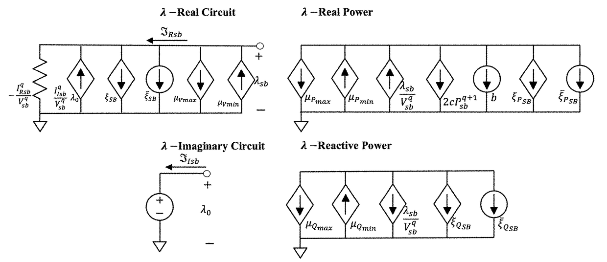
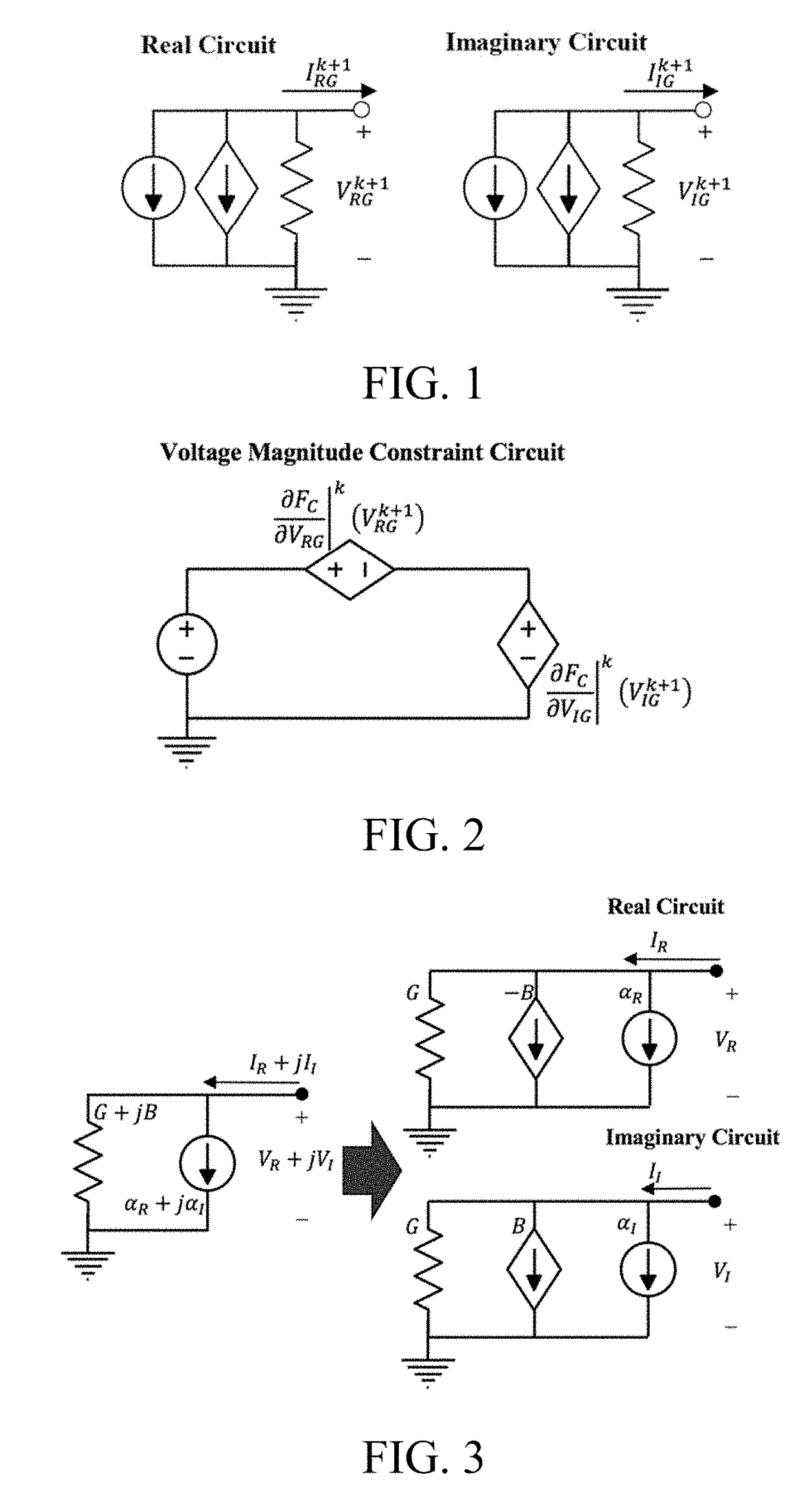
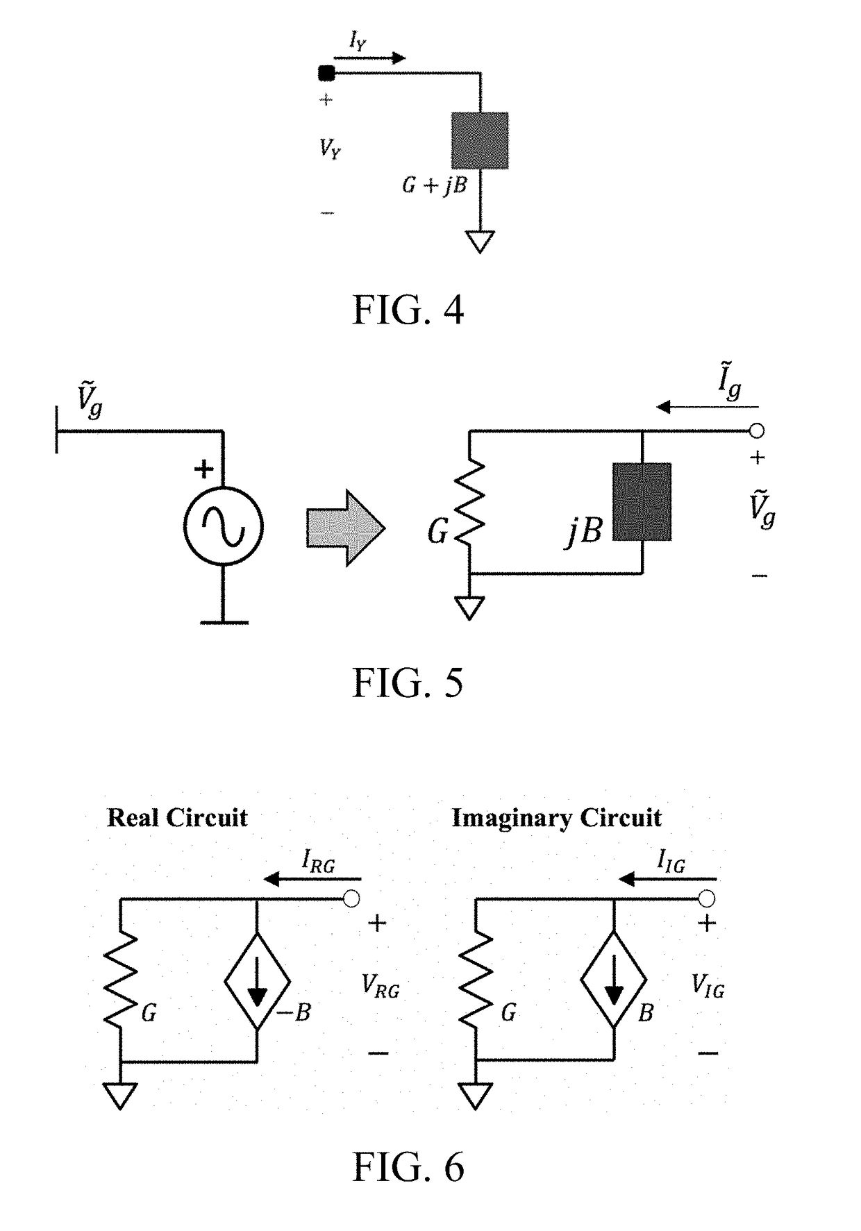
The present disclosure is directed to a method for formulating current and voltage conservation equations for an electrical power system using an equivalent circuit representation of the system. This representation includes a real sub-circuit and an imaginary sub-circuit, which are coupled via controlled voltage and current sources. The generators in the system are modeled by combinations of complex admittances and current or voltage sources of unknown value that represent their power delivery capabilities. The method includes running an optimization program to produce a minimum cost for operating the electrical power system based on the solution of control parameter values for the generator models in the system. The technical effect of this invention is to enable efficient formulation and optimization of power flow conservation equations for electrical power systems.

Problems solved by technology

It was soon realized, however, that the OPF problem formulated using the aforementioned power flow equations and variables represented an extremely nonconvex programming problem with many local optimal solutions, and it is presently recognized as a very difficult problem to solve.
Most importantly, due to highly nonlinear, non-convex constraints, the optimal power flow problem algorithms have changed little over the past decades.

Method used


Image

  • Methods and Software for Calculating Optimal Power Flow in an Electrical Power Grid and Utilizations of Same
  • Methods and Software for Calculating Optimal Power Flow in an Electrical Power Grid and Utilizations of Same
  • Methods and Software for Calculating Optimal Power Flow in an Electrical Power Grid and Utilizations of Same

Examples


example implementation

III. E Example Implementation of an OPF Solver in a Power Grid Network

[0166]FIG. 33 illustrates an example scenario 3300 in which an OPF solver 3304, made in accordance with aspects of the present invention, is used to solve for an OPF solution for a power supply system 3308 that includes a plurality of generators (shown collectively at element 3308A) and power grid equipment (shown collectively at element 3308B). Power supply system 3308 may be any relevant power supply system, such as a public utility grid, a private utility grid, a combination thereof, or a portion of any of these possibilities, among others. Depending on the character and nature of power supply system 3308, the power supply system may be controlled by one or more system operator 3312, such as a transmission system operator (TSO), an ISO, and / or a market dispatch, among others. Also depending on the character and nature of power supply system 3308, the power supply system may be monitored and / or regulated by one ...


PUM


Abstract

Methods of calculating optimal power flows (OPFs) in power transmission and distribution networks using equivalent-circuit formulations that allow the solutions to converge to corresponding global minima. In some aspects, network (circuit) elements are modeled using split circuits composed of real and imaginary parts. A variety of nonlinear OPF problem formulations are disclosed, including direct-solution formulations and iterative-solution formulations based on converting real and reactive power constraints to equivalent conductance / susceptance constraint. Also disclosed are a variety of techniques for solving the disclosed OPF problems, including new admittance-stepping homotopy techniques, among others. Software embodying disclosed methods is also described, as are example implementation scenarios.

Description

RELATED APPLICATION DATA[0001]This application claims the benefit of priority of U.S. Provisional Patent Application Ser. No. 62 / 497,854, filed on Dec. 5, 2016, and titled “Optimal power flow using equivalent circuit formulation,” which is incorporated by reference herein in its entirety.FIELD OF THE INVENTION[0002]The present invention generally relates to the field of electrical power generation, transmission and distribution. In particular, the present invention is directed to method and software for calculating optimal power flow in an electrical power grid and utilizations of same.BACKGROUND[0003]Power flow method based on iteratively solving the nonlinear power mismatch equations was first conceived of five decades ago, and it remains the standard for simulating transmission-level power grids. As indicated by its name, the objective of power flow is to simulate the net transfer of power within a power system, whereby each bus (a “node” in the grid) is characterized by four qua...

Claims


Application Information

Patent Timeline
IPC IPC(8): G06Q50/06H02J3/16G05B13/04
CPCG06Q50/06H02J2003/007G05B13/048H02J3/16H02J2203/20Y02B70/3225Y02E40/30Y02E40/70Y02E60/00Y04S10/50Y04S20/222Y04S40/20
Inventor JEREMINOV, MARKOPILEGGI, LAWRENCEPANDEY, AMRITANSHU
Owner CARNEGIE MELLON UNIV
Why Eureka
Try Eureka