

Home network system using z-wave network and home automation device connection method using same
a home network and home automation technology, applied in the field of home network systems, can solve the problems of complicated connection procedures, difficult for ordinary people to use devices, and wireless control of devices, and achieve the effects of improving the quality of life of users, easy control, and convenient us
Active Publication Date: 2018-06-07
KYUNG DONG ONE
View PDF5 Cites 2 Cited by
- Summary
- Abstract
- Description
- Claims
- Application Information
AI Technical Summary
Benefits of technology
The present invention is a home network system and a home automation device connection method using a Z-Wave network. The technical effects of this patent are as follows: a wider and more stable network can be configured for controlling home automation devices from outside, improving user quality of life; the connection method is simple and easy, allowing anyone to control the home automation devices with a portable terminal; the standard communication protocol based on Z-Wave allows any home automation device to be easily embedded and used without limitation in manufacturers as long as it is a home automation device using the wired / wireless Z-wave bridge; when configuring a wireless network, the main home automation device may function as a router, allowing the home automation devices in a wide area to communicate with each other, increasing the use range of devices that may communicate with each other.
Problems solved by technology
In particular, the wireless LAN does not have a routing function, and has low obstacle transmittance, thus it is difficult to wirelessly control the device in a house with a large area and many obstacles, a lot of information is required to be input at the time of connection, and a connection procedure is complicated, such that it is difficult for an ordinary person to use the device.
However, since protocol schemes for controlling a smart device of manufacturers are different from each other, it may be difficult to implement interworking, and since most wireless communication frequencies using the wireless LAN use 2.4 GHz frequency band, data loss caused by frequency collision may not be avoided.
Method used
View moreImage
Smart ImageViewing Examples

Examples
Embodiment Construction
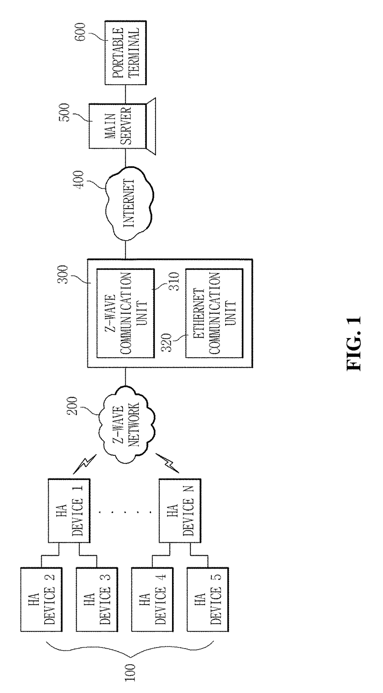
[0074]100; Home automation device[0075]200; Z-Wave network[0076]300; Wired / wireless Z-Wave bridge[0077]310; Z-Wave communication unit[0078]320; Ethernet communication unit[0079]400; Internet[0080]500; Main server[0081]600; Portable terminal
INDUSTRIAL APPLICABILITY
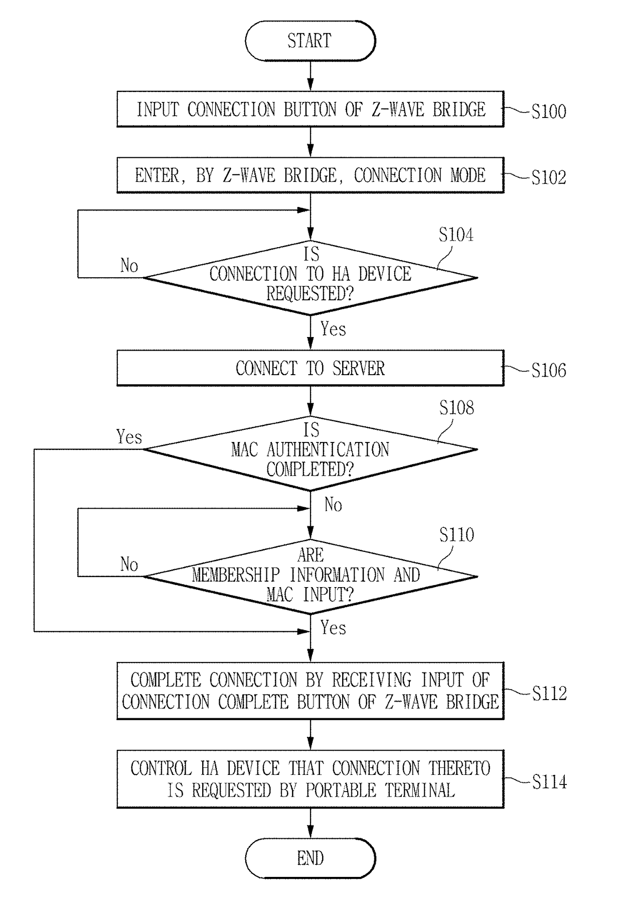
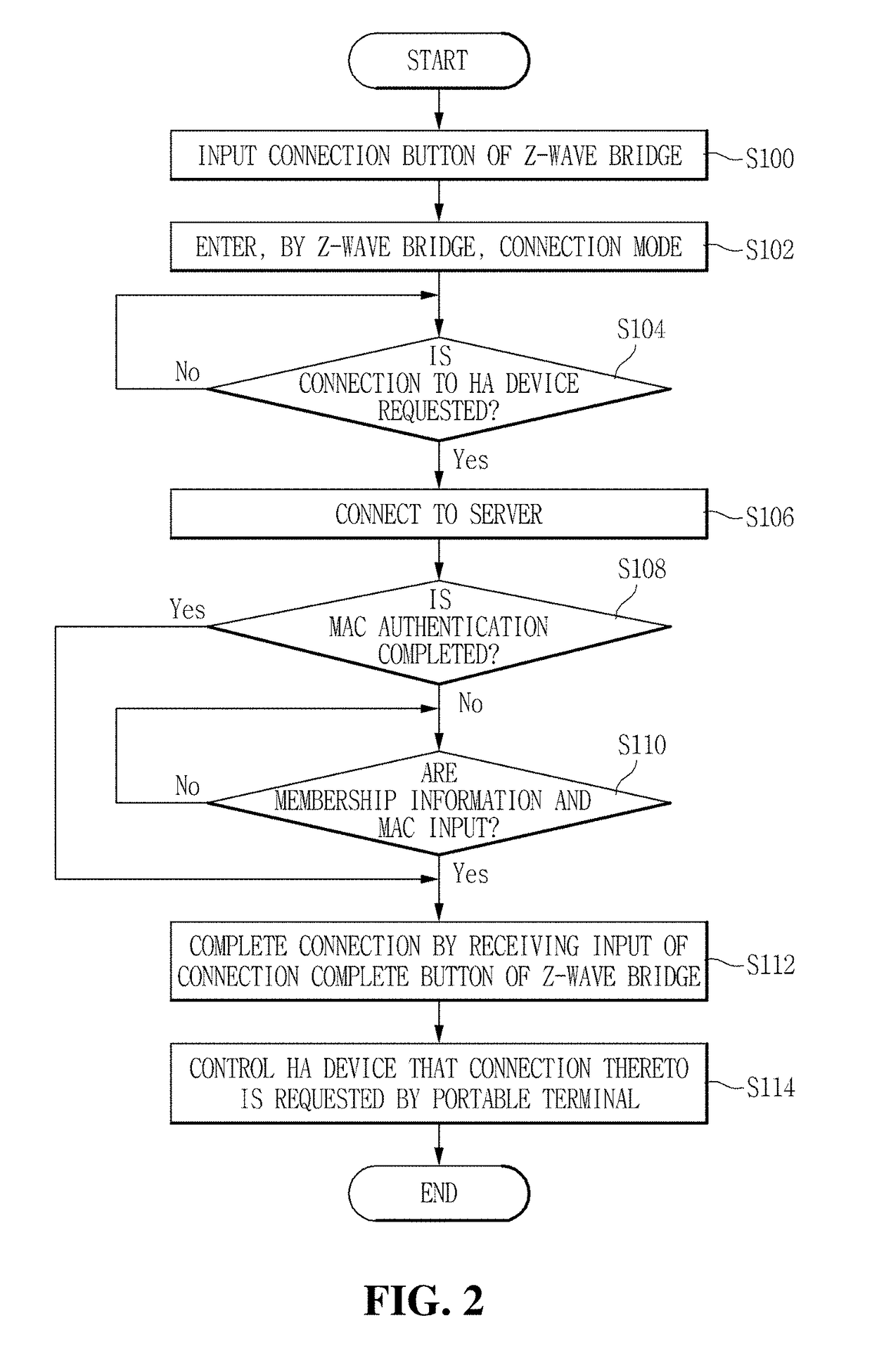
[0082]The present invention may be used in a field of home network system using a Z-Wave network, in which a home automation device is connected to a Z-Wave network system to thereby enable a stable and wide-range remote control by an external portable terminal, and an easy connection method by MAC authentication of a bridge connecting between the home automation device and the portable terminal is used to thereby secure user convenience.
Login to View More PUM
 Abstract
A home network system using a Z-Wave network according to the present invention includes: at least one home automation device connected to the Z-Wave network configuring a wireless network such that the device's state is remotely controlled by a portable terminal or a notification is provided to the portable terminal; a wired / wireless Z-Wave bridge including a Z-Wave communication unit and an Ethernet communication unit, having a unique MAC address, and connecting the portable terminal that is given access to the wired / wireless Z-Wave bridge by a main server through authentication of the unique MAC address, to the Z-Wave network through the Internet; and the main server connected to the wired / wireless Z-Wave bridge or the portable terminal through the Internet, providing an application for a remote control when requested by the portable terminal, and performing authentication for giving access to the wired / wireless Z-Wave bridge. According to the present invention, anyone can easily control a home automation device through a portable terminal by configuring a Z-Wave network system and inputting a unique MAC address.
Description
TECHNICAL FIELD[0001]The present invention relates to a home network system, and more particularly, to a home network system using a Z-Wave network and a home automation device connection method using the same, in which a home automation device is connected to a Z-Wave network system to thereby enable a stable and wide-range remote control by an external portable terminal, and an easy connection method by MAC authentication of a bridge connecting between the home automation device and the portable terminal is used to thereby secure user convenience.BACKGROUND ART[0002]Z-Wave is a wireless communications protocol with interoperability that is developed by Zensys which is a Danish company and Z-Wave Alliance, is designed for an apparatus requiring low power and low bandwidth such as home automation device, a sensor network, or the like, and uses a bandwidth with a transmission speed of 9,600 bit / s or 40 Kbit / s and a Gaussian frequency-shift keying (GFSK) modulation scheme.[0003]Furthe...
Claims
Login to View More Application Information
Patent Timeline
 IPC IPC(8): H04L29/06H04L12/28H04L12/12
CPCH04L63/0876H04L12/2816H04L12/12G05B2219/2642H04L9/3231H04L12/2818H04L12/2834H04L67/125H04W4/33H04W12/06H04L9/32H04L12/28Y02D30/50
InventorOH, SE YOUNG
OwnerKYUNG DONG ONE