Autonomous Movement System

a technology of autonomous movement and movable objects, applied in the direction of vehicle position/course/altitude control, process and machine control, etc., can solve the problems of non-autonomous movement, lack of consideration for prompting for movable objects, and inconvenient use of movable objects, so as to improve ride comfort, reduce speed, and reduce costs

Active Publication Date: 2018-06-14
DOOG
View PDF0 Cites 23 Cited by
  • Summary
  • Abstract
  • Description
  • Claims
  • Application Information

AI Technical Summary

Benefits of technology

[0008]According to the present disclosure, a movable object that autonomously travels with a user riding thereon is equipped with a sensing device for detecting traveling-route reflector across a wide range of areas, thereby being capable of providing an autonomous movement system with improved ride comfort. The detection of the traveling-route reflector across a wide range of areas allows achievement of traveling control, such as gradual deceleration prior to entering a curve, speed regulation based on the turning radius at the curve so that the centrifugal force is not too great, and the like. Furthermore, the movable object can detect a branch point or an intersection in advance, reduce the speed, and notify the user for prompting the user to instruct which direction to proceed. Furthermore, for a movable object that autonomously travels with an item loaded thereon, a single sensing device detects the traveling-route reflector and also serves as a safety sensor for avoiding collision with any other objects therearound. This would expectedly result in cost reduction.

Problems solved by technology

A conventional technology-applied movable object that autonomously travels with a person riding thereon lacks consideration for ride comfort for the user.
In addition, such a movable object lacks consideration for prompting the user to determine which route to proceed at a branch point, an intersection, or the like, and also lacks consideration for semi-autonomous movement.
For example, when a user rides a conventional technology-based movable object, the user may experience discomfort from a great centrifugal force created whenever the movable object does not sufficiently decelerate while turning through a curve.

Method used


Image

  • Autonomous Movement System
  • Autonomous Movement System
  • Autonomous Movement System

Examples


embodiment 1

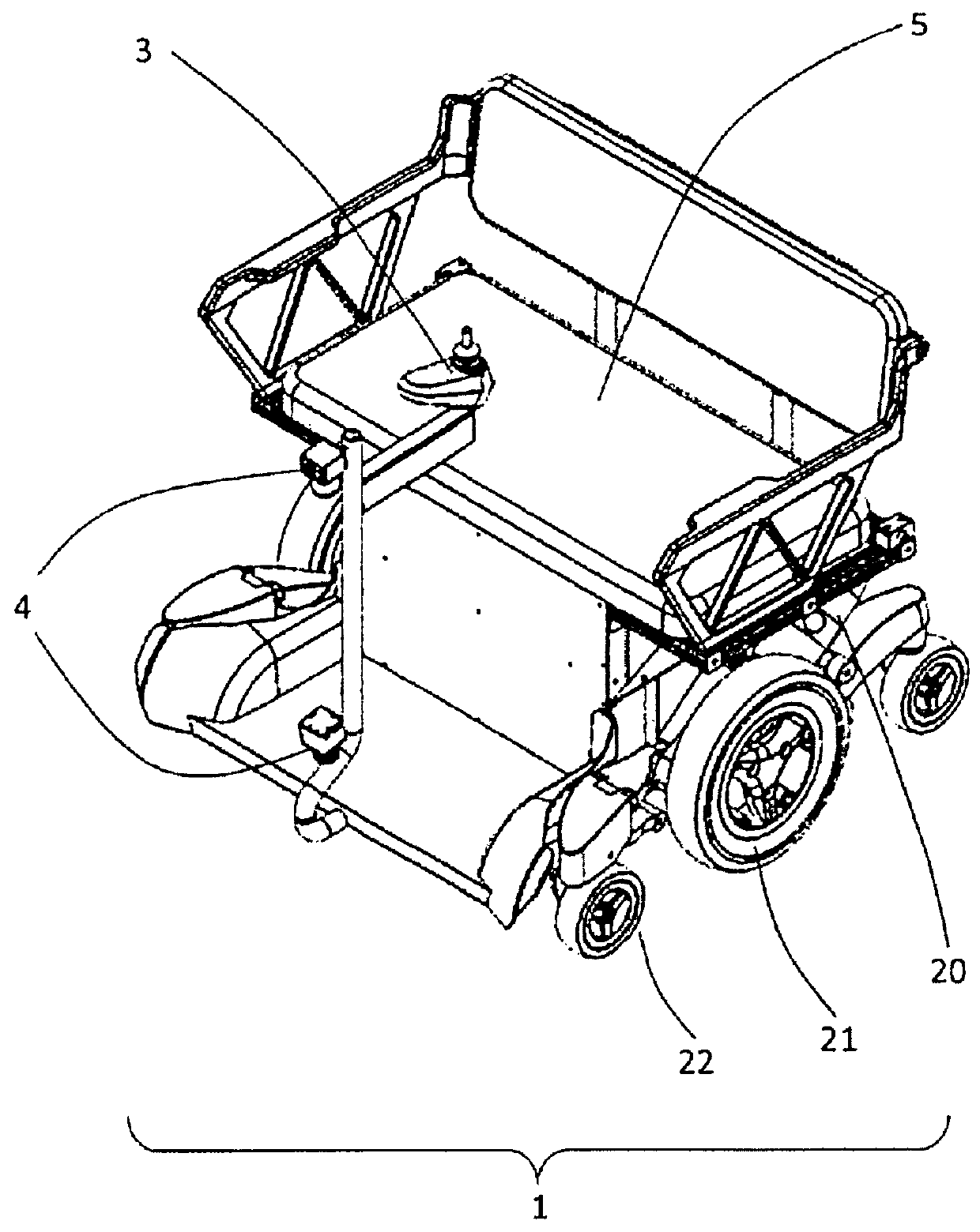
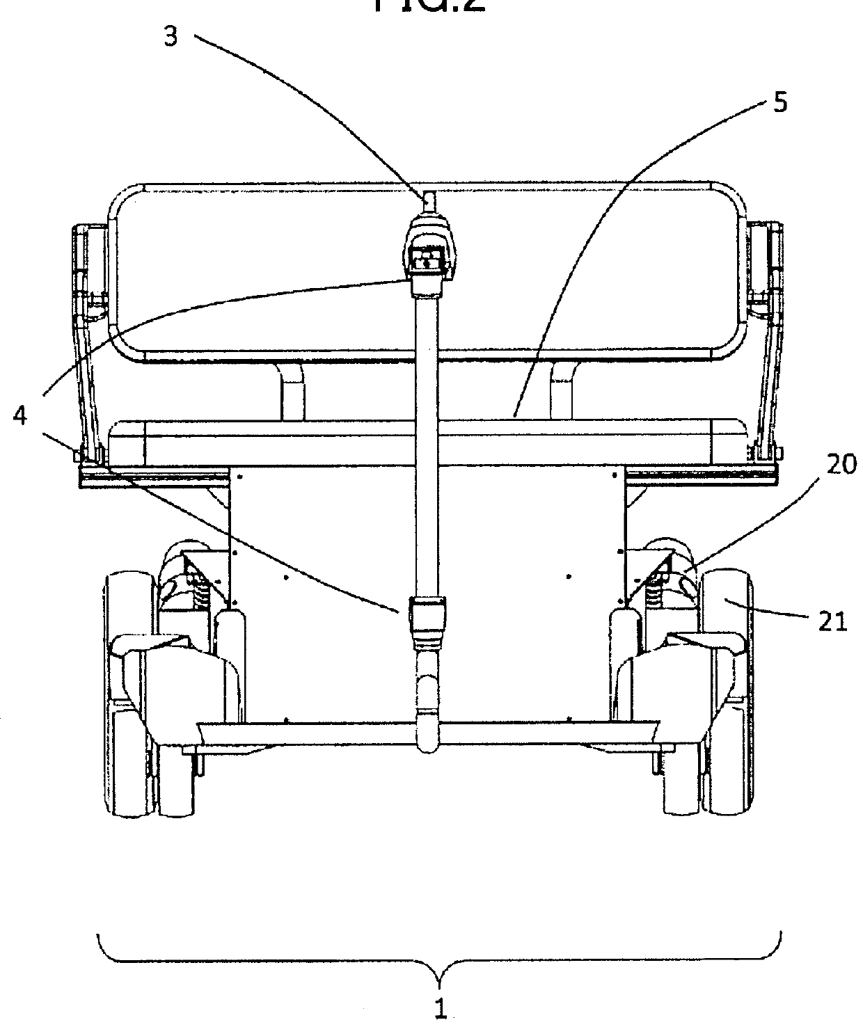
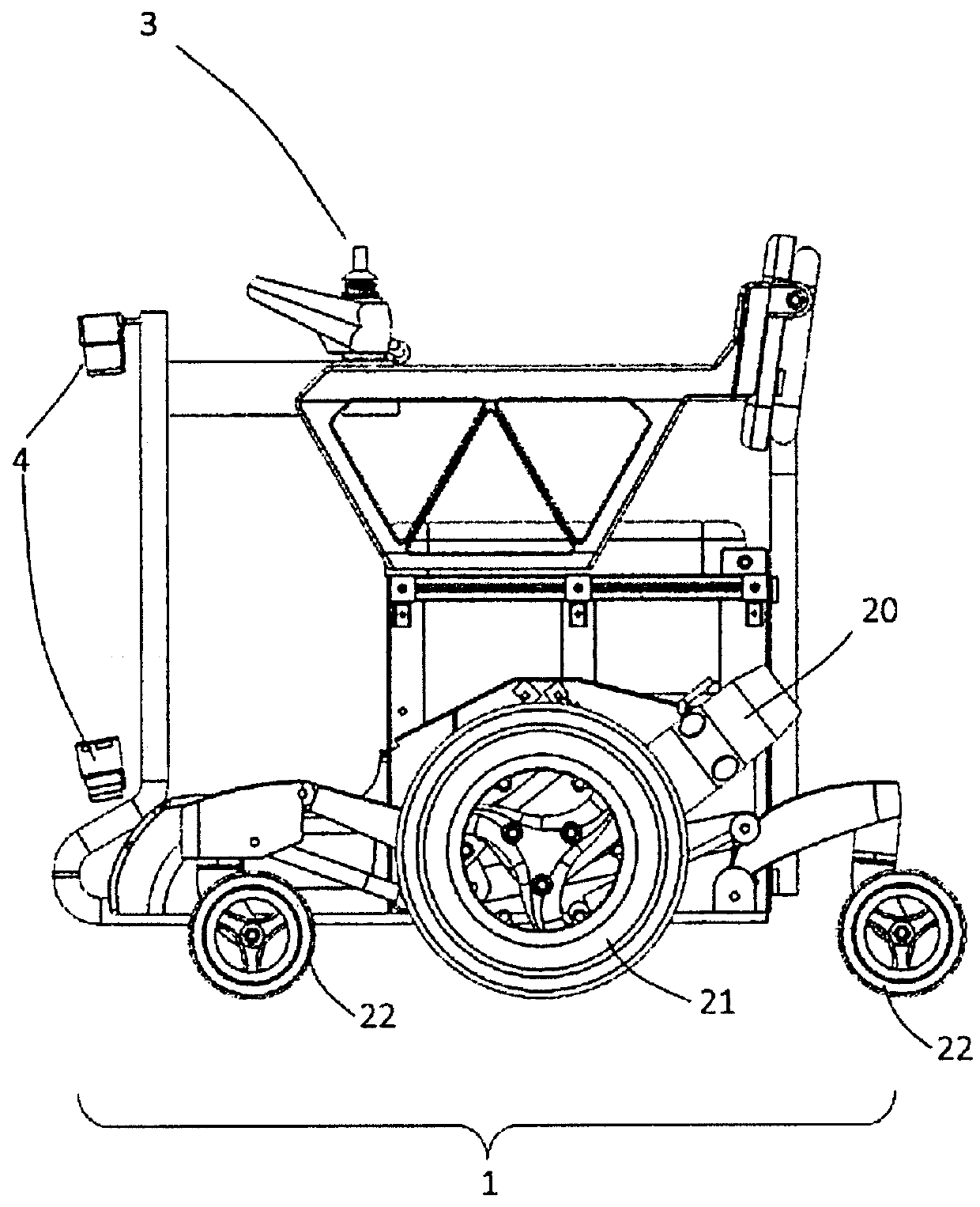
[0026]A movable object according to a first embodiment of the present disclosure is described with reference to FIGS. 1-7. First, a main body of the movable object according to the present embodiment is described with reference to FIGS. 1-3. FIG. 1 is an exterior view of an electric wheelchair, which is a type of the movable object. FIG. 2 is a front view of the movable object, and FIG. 3 is a left side view of the movable object.

[0027]The reference sign 1 in FIGS. 1-3 denotes an electric wheelchair-type movable object according to the present embodiment. The reference sign 5 in FIG. 1 denotes a seat for a user. The movable object 1 includes drive wheels 21, casters 22, and motors 20 for rotating the drive wheels 21. The motors 20 are electric motors in the present embodiment. Two electric motors, one on the right and one on the left side, are installed so as to respectively drive the two drive wheels 21 that are opposed to each other in the horizontal direction. Through their respe...


PUM


Abstract

A movable object includes a sensing device for detecting traveling-route reflector on a travel surface so that a region outside a floor projection region of the movable object, in particular the traveling-route reflector forward, can be detected. Detecting the traveling-route reflector across a wide range of areas allows traveling control, such as gradual deceleration before entering a curve, speed regulation based on a turning radius at the curve so that centrifugal force on a rider or load is not too great. Also the movable object can detect a branch point or an intersection beforehand, decelerate, and notify the user for user's instruction regarding the traveling direction. Furthermore, for a movable object autonomously traveling with an item mounted thereon, a single sensing device detects the traveling-route reflector and also serves as a safety sensor for avoiding collision with any other objects therearound.

Description

TECHNICAL FIELD[0001]The present disclosure relates to a movable object that moves along a predetermined traveling route, transporting a person or an item. Examples of the movable object include an electric wheelchair, a crawler robot, an omnidirectionally-movable vehicle using omnidirectional wheels, and the like. The present disclosure particularly relates to a configuration of a movable object that travels autonomously without the need of manipulation along a route prearranged on the ground.BACKGROUND ART[0002]Autonomous movement technologies have conventionally been used for conveyance of items within factories and the like. For example as described in Unexamined Japanese Patent Application Kokai Publication No. 2004-86453 (Patent Literature 1), an automated guided vehicle configured to travel along an intended traveling route by utilizing magnetic tape on the ground and a magnetic sensor disposed on the bottom of the vehicle is used in factories, warehouses, and the like. The a...

Claims


Application Information

Patent Timeline
Patent Type & Authority Applications(United States)
IPC IPC(8): G05D1/02A61G5/04
CPCG05D1/0244G05D1/0236G05D1/0248G05D1/024A61G5/043A61G5/04A61G5/10A61G2203/14A61G2203/16A61G2203/20A61G2203/22A61G2203/72A61G5/1051G05D2201/0206
Inventor OSHIMA, AKIRAKUNIYOSHI, HIROYASU
Owner DOOG
Why Eureka
Try Eureka