Optical detection device and facility management system

a technology of optical detection and facility management, applied in the direction of total factory control, programme control, electric programme control, etc., can solve the problems of increasing etc., to prevent an increase in costs or process steps, enhance power conversion efficiency, and improve the operation rate of the facility

Inactive Publication Date: 2018-06-14
JTEKT CORP
View PDF5 Cites 2 Cited by
  • Summary
  • Abstract
  • Description
  • Claims
  • Application Information

AI Technical Summary

Benefits of technology

[0008]With the optical detection device according to the above aspect, the optical sensor and the optical-detection-side communication unit operate with power into which light from the light source of the indication lamp is converted and the optical-detection-side communication unit transmits an optical detection signal or the like in a wireless manner. Accordingly, since a wire for supply of power from an existing facility or a wire for communication with an external device is not necessary and the optical detection device can operate simply by arranging the optical detection device in the vicinity of the indication lamp, it is possible to prevent an increase in costs or the number of process steps. Since the photoelectric conversion unit converts light from the light source of the indication lamp into power, the optical detection device can operate even in an indoor place which solar light does not reach and a device independent of the surrounding environment can be constituted. Since the photoelectric conversion unit converts light from the indication lamp that is closer to the photoelectric conversion unit than indoor illumination, it is possible to enhance power conversion efficiency in comparison with light from indoor illumination.
[0009]According to another aspect of the invention, there is provided a facility management system including: the optical detection device according to the above-described aspect that is attached to a facility; and a facility managing device that includes a management-side communication unit receiving a signal transmitted from the optical-detection-side communication unit of the optical detection device attached to the facility and an information display unit displaying information of a signal received by the management-side communication unit and that manages the facility. According to this facility management system, since the operation conditions of the facility can be comprehensively managed by the facility managing device, it is possible to achieve improvement in an operation rate of the facility and reduction in a burden on an operator in addition to the advantages of the optical detection device.

Problems solved by technology

Accordingly, costs or the number of process steps increases.
However, in the device described in JP 2004-006291 A, it is necessary to acquire a power source for operation from the existing facility, and thus, costs or the number of process steps increase due to addition of wires, breakers, or the like.

Method used


Image

  • Optical detection device and facility management system
  • Optical detection device and facility management system
  • Optical detection device and facility management system

Examples


Embodiment Construction

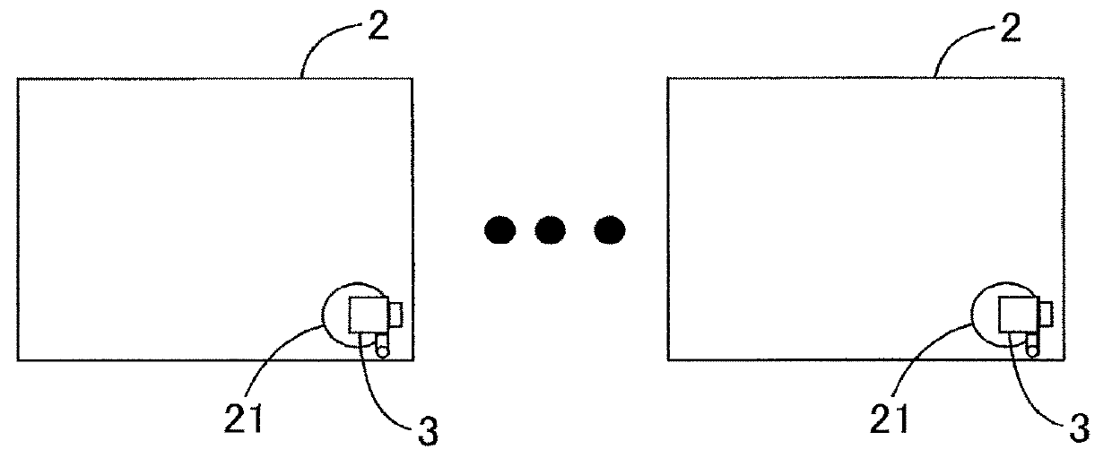
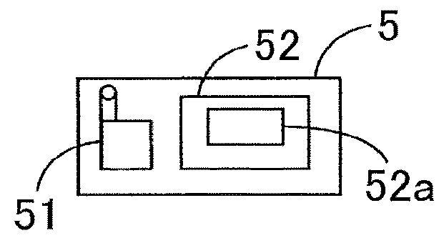
[0017]A facility management system including an optical detection device according to an embodiment of the invention will be described below with reference to the accompanying drawings. As illustrated in FIG. 1, the facility management system 1 includes a plurality of facilities 2, optical detection devices 3 each attached to a corresponding one of the facilities 2, and a facility managing device 5 that manages the facilities 2.

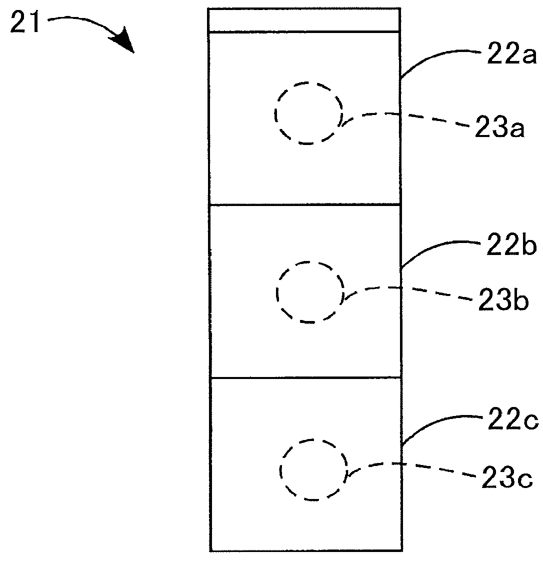
[0018]Each facility 2 is, for example, a machining device that can cut or grind a workpiece. A signal indication lamp 21 that notifies operation conditions of each facility 2 by emitting light is disposed in an upper part of the facility 2. As illustrated in FIG. 2, the signal indication lamp 21 is typical and has a configuration in which translucent plastic cases 22a. 22b, and 22c of a hollow cylindrical shape are stacked in three stages and light sources 23a, 23b, and 23c such as LEDs are arranged in the plastic cases 22a, 22b, and 22c, respectively.

[0019]T...


PUM


Abstract

An optical detection device includes: an optical sensor configured to detect light from a light source of an indication lamp; an optical-detection-side communication unit configured to wirelessly transmit at least an optical detection signal of the optical sensor; and a photoelectric conversion unit configured to convert light from the light source into power and to store the power. The optical sensor and the optical-detection-side communication unit operate using the power stored in the photoelectric conversion unit.

Description

INCORPORATION BY REFERENCE[0001]The disclosure of Japanese Patent Application No. 2016-238343 filed on Dec. 8, 2016 including the specification, drawings and abstract, is incorporated herein by reference in its entirety.BACKGROUND OF THE INVENTION1. Field of the Invention[0002]The invention relates to an optical detection device that detects light and a facility management system that includes the optical detection device.2. Description of the Related Art[0003]When operation conditions of an existing facility can be transmitted from the existing facility to the outside, an operator or a manager can easily understand the operation conditions to achieve improvement in production efficiency. However, in order to transmit operation conditions of an existing facility to the outside, an existing control device such as software (a ladder circuit) of a controller (PLC) of the existing facility need to be changed or a new control device such as a relay component for inputting an input signal...

Claims


Application Information

Patent Timeline
Patent Type & Authority Applications(United States)
IPC IPC(8): G08G1/07G05B19/05
CPCG08G1/07G05B19/05G05B19/41845G05B2219/33273G05B19/042G05B19/4185Y02P90/02H04B10/807G05B19/418
Inventor NAKAGAWA, TOMOYUKIMURAYAMA, SAKON
Owner JTEKT CORP
Why Eureka
Try Eureka