Hydraulic suspension system for a vehicle, a vehicle being provided with such a system and a method for damping an Anti-roll function of a vehicle

a suspension system and hydraulic technology, applied in the direction of suspensions, interconnection systems, resilient suspensions, etc., can solve the problems of increasing the sideways rolling or lateral vibration of the vehicle, reducing the cross-sectional area of fluid communication paths, dampening or delay the cross-coupling between the cylinders, etc., to achieve the effect of reducing the flow ra

Active Publication Date: 2018-06-21
VOLVO CONSTR EQUIP AB
View PDF0 Cites 2 Cited by
  • Summary
  • Abstract
  • Description
  • Claims
  • Application Information

AI Technical Summary

Benefits of technology

[0005]It is desirable to provide a hydraulic suspension system having both satisfactory anti-roll functionality and satisfactory prevention of lateral vibrations.
[0038]The provision of flow restriction elements has proven to be a simple and yet efficient manner in reducing the cross-sectional area, and thereby the maximum potential flow rate, of a fluid connection path.

Problems solved by technology

Such a hydraulic anti-roll bar functions works well for some driving conditions, while it has a tendency to increase the sideways rolling, or lateral vibrations, of the vehicle in other driving conditions, such as when driving over an obstacle with one or more of the wheels of one side of the vehicle.
Hence, when a sudden event that affects one or both of the hydraulic cylinders occurs, the reduced cross-sectional areas of the fluid communication paths dampen or delay the cross-coupling between the cylinders.
Hence, when a sudden event that affects one or both of the hydraulic cylinders occurs, the reduced cross-sectional areas of the fluid communication paths dampen the cross-coupling between the cylinders.

Method used


Image

  • Hydraulic suspension system for a vehicle, a vehicle being provided with such a system and a method for damping an Anti-roll function of a vehicle
  • Hydraulic suspension system for a vehicle, a vehicle being provided with such a system and a method for damping an Anti-roll function of a vehicle
  • Hydraulic suspension system for a vehicle, a vehicle being provided with such a system and a method for damping an Anti-roll function of a vehicle

Examples


Embodiment Construction

[0045]The present invention will now be described more fully hereinafter with reference to the accompanying drawings, in which exemplary embodiments of the invention are shown. The invention may, however, be embodied in many different forms and should not be construed as limited to the embodiments set forth herein; rather, these embodiments are provided for thoroughness and completeness, and fully convey the scope of the invention to the skilled addressee. Like reference characters refer to like elements throughout the description.

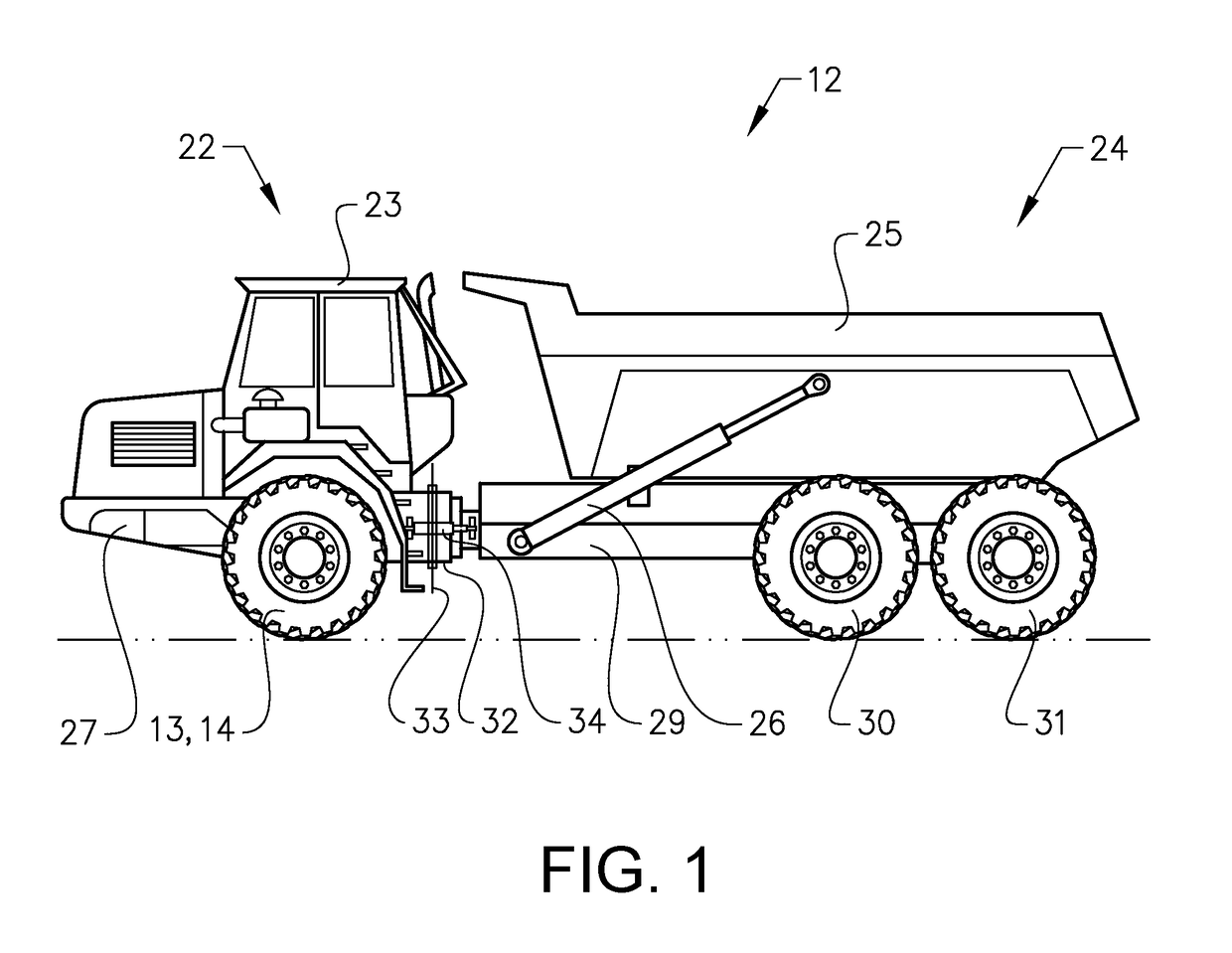
[0046]FIG. 1 is an illustration of a working machine 12 in the form of an articulated hauler having a front section 22 with a cab 23 for an operator and a rear section 24 with a dump body or container 25 for receiving, transporting and tipping a load. The present invention may beneficially be implemented in such a working machine. The front section has a front frame 27 and a pair of wheels 13, 14 (of which only one is visible) suspended from the front fram...


PUM


Abstract

A hydraulic suspension system is provided for a vehicle, the system including at least a first hydraulic cylinder and a second hydraulic cylinder, each of the hydraulic cylinders including a first chamber and a second chamber, at least four hydraulic accumulators, and at least a first and a second fluid communication path. The first chamber of the first hydraulic cylinder, and the second chamber of the second hydraulic cylinder are in fluid communication with each other by means of the first fluid communication path, and the first chamber of the second hydraulic cylinder and the second chamber of the first hydraulic cylinder are in fluid communication with each other by means of the second fluid communication path, wherein a first hydraulic accumulator is in fluid communication with the first fluid communication path by means of a first accumulator fluid communication path and a second hydraulic accumulator is in fluid communication with the first fluid communication path by means of a second accumulator fluid communication path, wherein a connection point between the first accumulator fluid communication path and the first fluid communication path is distanced from a connection point between the second accumulator fluid communication path and the first fluid communication path, and wherein a third hydraulic accumulator is in fluid communication with the second fluid communication path by means of a third accumulator fluid communication path and a fourth hydraulic accumulator is in fluid communication with the second fluid communication path by means of a fourth accumulator fluid communication path, wherein a connection point between the third accumulator fluid communication path and the second fluid communication path is distanced from a connection point between the fourth accumulator fluid communication path and the second fluid communication path.

Description

BACKGROUND AND SUMMARY[0001]The present invention relates to a hydraulic suspension system for a vehicle. The present invention also relates to a vehicle being provided with a hydraulic suspension system and a method for damping an anti-roll function of a hydraulic suspension system for a vehicle.[0002]The invention is applicable on working machines within the fields of industrial construction machines or construction equipment; in particular articulated haulers. Although the invention will be described with respect to an articulated hauler, the invention is not restricted to this particular vehicle, but may also be used in working machines, such as wheel loaders and backhoe loaders. It may also be used in e.g. trucks, buses or cars.[0003]Vehicles, for example articulated haulers, today are most often provided with suspension systems in order to e.g. provide for a better travel comfort by absorbing e.g. road irregularities, bumps and ledges. An articulated hauler is provided with a ...

Claims


Application Information

Patent Timeline
Patent Type & Authority Applications(United States)
IPC IPC(8): B60G21/073B60G21/02B60G9/00
CPCB60G21/073B60G21/026B60G9/00B60G2300/026B60G2300/09B60G2202/15B60G2204/82
Inventor FREDRIKSSON, VILHELM
Owner VOLVO CONSTR EQUIP AB
Why Eureka
Try Eureka