
Safety cap spout

a safety cap and spout technology, applied in the field of safety cap spout, can solve the problems of affecting and affecting the safety of use, so as to improve the accuracy of breakage

Active Publication Date: 2018-06-21
JOONGANG PLATEC CO LTD
View PDF8 Cites 13 Cited by
  • Summary
  • Abstract
  • Description
  • Claims
  • Application Information

AI Technical Summary

Benefits of technology

The present invention aims to improve the accuracy of breakage in the latched state and expose a certain portion of the broken guarantee seal to the outside. To achieve this, the guarantee seal is coupled to the latching protrusion of the body, and the latching protrusion is selectively latched to a plurality of latching grooves formed in the guarantee seal. This solves the conventional problem of inaccuracy in breakage. When the cap and the body are assembled to each other, the latching protrusion slides on the upper surface of the guarantee seal and is screw-tightened so as to be latched to the latching groove. This ensures accurate breakage of the guarantee seal upon opening, and the guarantee seal is dropped down as it is accurately broken and exposed. The technical effect is the improved accuracy of breakage and easy and accurate exposure of the broken guarantee seal.

Problems solved by technology

However, the disadvantage of the cap is that since the upper end of the cap is blocked to block the outflow hole of the body, if infants accidentally or carelessly swallow the cap, there is a risk in which the airway of the infants may be blocked.
However, although such a safety cap does not block the airway, there is a molding problem that the guarantee seal may not be formed directly under the inner cap and may be formed only when the guarantee seal is spaced outward from a lower side of the cap.
In addition, when formed as described above, the guarantee seal is obscured by the outer cap, so that the guarantee seal is not easily exposed to the outside even if it is broken.
Therefore, there might be inconvenience for a user to check the temper-proof state.
However, the problem that the guarantee seal cannot be seen because the guarantee seal is located at a lower end of the inner cap and the problem that the guarantee seal cannot be formed directly under the inner cap still remain.
However, users often do not notice much of the actual condition of the guarantee seal because the guarantee seal is obscured by the outer cap constituting the safety cap.
This means that the breakage condition of the guarantee seal may not be immediately seen to the users who only perform the checking randomly or accidentally.
However, in this case, the design of a product is not good, and not suitable for a practical product design.
However, in such a case, since the guarantee seal cannot be positioned directly under the inner cap due to the molding problem, the guarantee seal is spaced outwards from the inner cap while being positioned under the inner cap.
In addition, when it is desired to provide such reinforcing fins for support, there is a difficulty in forming a mold or in injection molding, and productivity is degraded because the flowability of an injection-molded product is not good.
Accordingly, the defective rate is high, so that it is difficult to perform actual mass production.
However, this may result in a problem that a deformed shape of the outer cap may spoil the design, which may cause problems in practical use.

Method used


Image

  • Safety cap spout
  • Safety cap spout
  • Safety cap spout

Examples


first embodiment

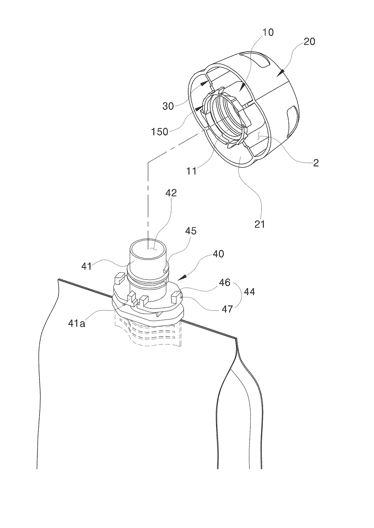
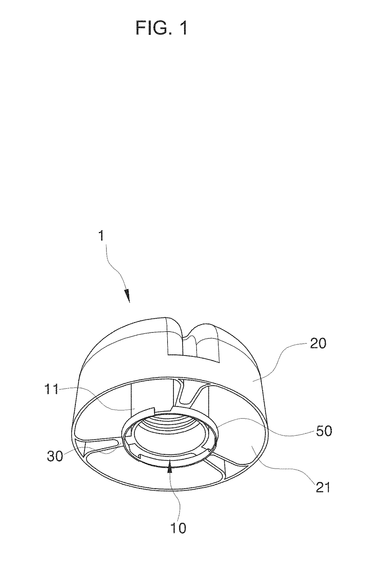
[0050]First, FIGS. 1 to 9 show a safety cap spout according to the present invention.

[0051]Reference numeral 1 denotes a cap 1, which is preferably injection molded with plastic and can be screw-tightened and screw-loosened on a straw 41 of a body 40 fused to a pouch-type container 100, which is particularly a pouch-type container 100 for a liquid for children, such as fruit juice and various drinks.

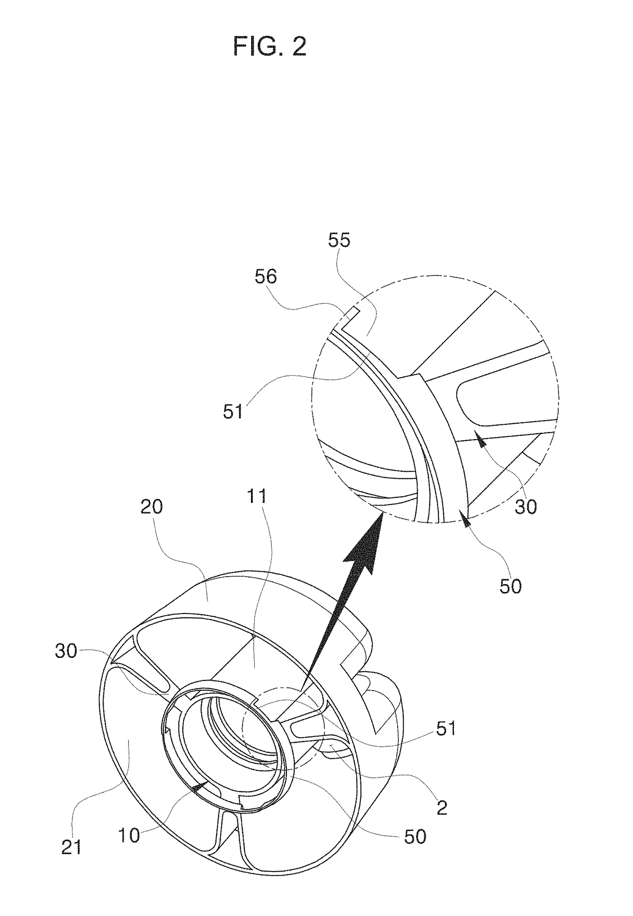
[0052]The cap 1 includes: an inner cap 10 having a tubular body formed along a central axis X; and an outer cap 20 having an annular wall part 21 that has an inner wall connected to an outer wall of the inner cap 10 by a tab 30, wherein a vent hole 2 is formed between at least two tabs 30.

[0053]In other words, the annular wall part 21 is connected to the tab 30 while being radially spaced apart from the inner cap 10, and the vent hole 2 formed thereby and formed by the tabs 30 arranged at a predetermined interval provides a passage for allowing air to pass there through, so that choking ...

second embodiment

[0069]In addition, FIGS. 10 to 18 show a safety cap spout according to the present invention.

[0070]In this case, a guarantee seal 150 having a shape of a circular band that has an inner diameter relatively larger than an outer diameter of the inner cap 10 is provided at a lower end of the inner cap 10.

[0071]In the guarantee seal 150, curved cut-out parts 152 provided at lower ends of the tabs 30 are connected to each other by weak parts 151, a lower rim 153 having a shape of a circular band is formed at a bottom of the guarantee seal 150, and an upper rim 154 having a plurality of latching grooves 155 is formed at a top of the guarantee seal 150.

[0072]The guarantee seal 150 is provided to notify that the guarantee seal 150 is broken by the cut-out part 152 being released outwards as the weak part 151 is broken by the latching protrusion 44.

[0073]In detail, the cut-out part 152 is coupled to one end of the weak part 151 at one side of a curved part 157 coupled to the tab 30 through a...


PUM

PropertyMeasurementUnit
pressureaaaaaaaaaa
shapeaaaaaaaaaa
thicknessesaaaaaaaaaa

Abstract

The present invention relates to a spout for a pouch-type container in which a cap is coupled to a body fused to a pouch-type container body in a one-touch manner, and more particularly, to a spout which is applied to a safety cap and allows to accurately cut the guarantee seal and expose a cut-off state to an outside of an outer cap upon opening of the safety cap so as to achieve accurate opening and easy recognition, in which a guarantee seal is coupled to a latching protrusion of the body such that the latching protrusion is positioned on the guarantee seal and selectively latched to a plurality of latching grooves formed in the guarantee seal.

Description

CROSS-REFERENCE TO RELATED APPLICATION(S)[0001]This application claims the benefit under 35 U.S.C. § 119(a) of a Korean patent application filed on Dec. 19, 2016 in the Korean Intellectual Property Office and assigned Serial number 10-2016-0173998 and of a Korean patent application filed on Jul. 25, 2017 in the Korean Intellectual Property Office and assigned Serial number 10-2017-0093852, the entire disclosure of each of which is hereby incorporated by reference.BACKGROUND OF THE INVENTION1. Field of the Invention[0002]The present invention relates to a configuration in which a safety cap is coupled to a body fused to a pouch-type container body in a one-touch manner, and more particularly, to a configuration which allows to accurately cut a guarantee seal and expose a cut-off state to an outside of an outer cap upon opening of the safety cap so as to achieve accurate opening and easy recognition.2. Description of the Related Art[0003]A spout for safely sealing and discharging cont...

Claims


Application Information

Patent Timeline
Patent Type & Authority Applications(United States)
IPC IPC(8): B65D41/34B65D75/58B65D47/32
CPCB65D41/34B65D75/5883B65D47/32B65D41/3404B65D2213/00
Inventor KWON, OH-JOON
Owner JOONGANG PLATEC CO LTD
Learn More