Control system for a wind turbine

a control system and wind turbine technology, applied in the direction of engine control, motors, image data processing, etc., can solve the problems of unable to monitor the blade, and not being able to install sensors

Active Publication Date: 2018-06-21
VESTAS WIND SYST AS
View PDF29 Cites 5 Cited by
  • Summary
  • Abstract
  • Description
  • Claims
  • Application Information

AI Technical Summary

Benefits of technology

[0011]The control system of the present invention provides a simple, reliable and effective way to monitor a wind turbine blade and / or control operation of one or more wind turbine blades in dependence on a detected change in the shape or orientation of a blade of the wind turbine in use. The control system may reduce or eliminate the need to include a large number of individual sensors such as strain sensors and accelerometers in the blade that are each configured to measure a specific quantity at their respective locations. However, it will be appreciated that the blade may still be provided with additional sensors that may also be used in monitoring the state of the blade.
[0028]The control system may be configured to automatically select the target feature from a plurality of recognisable features. The selection of the target feature may be performed during an initial calibration process for the control system, for example by selecting the target feature from a plurality of recognisable features extracted from an initial reference image. The control system may therefore be capable of independently selecting a suitable target feature to monitor the position of without being initially focussed on a specific target feature and without requiring any user input to select the target feature. In this way it may not be necessary to rely on any pre-selected features having known positions. This is in contrast to known camera based blade monitoring systems which focus on a pre-determined visible marker provided on a blade and require pre-knowledge of the exact position of the marker with respect to the blade (for example the position of the marker along the length of the blade) in order to determine blade deflection.

Problems solved by technology

However, installing a large number of individual sensors in a wind turbine blade is time consuming and expensive, and it may not be possible to install sensors in all locations for which a reading may be desired.
In addition, blade monitoring systems that rely on data from a large number of individual sensors may be impaired if one or more of the sensors stop functioning correctly, and sensors in certain locations may be difficult to repair or replace if damaged.
However, such a system requires one or more markers to be mounted within the wind turbine blade in exact known positions, which presents challenges during manufacture and maintenance of the wind turbine blade.
However, wind turbine controllers configured to operate in this manner may be complicated, and rely on data being received from a complex system of sensors as described above.

Method used


Image

  • Control system for a wind turbine
  • Control system for a wind turbine
  • Control system for a wind turbine

Examples


Embodiment Construction

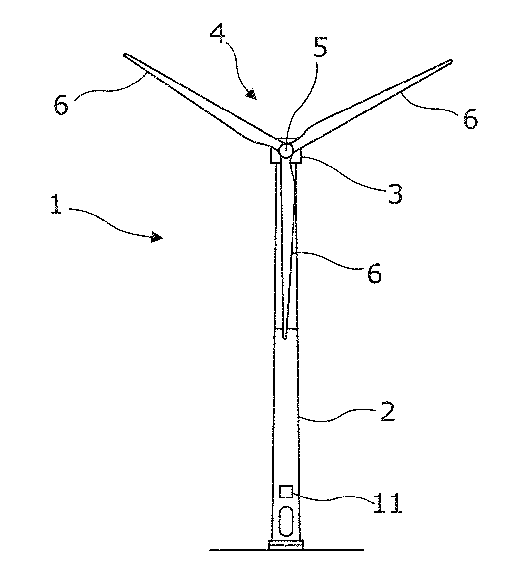
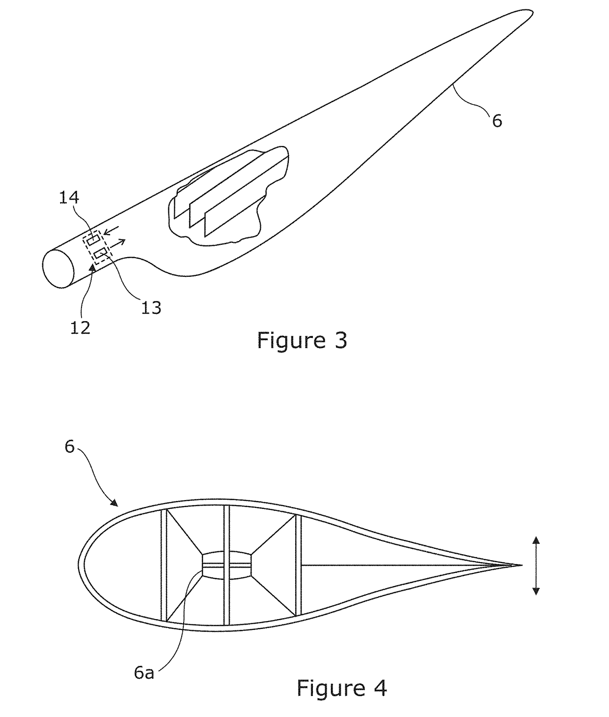
[0045]FIG. 1 schematically illustrates a wind turbine 1. The wind turbine may be either an on-shore wind turbine or an off-shore wind turbine. The wind turbine 1 comprises a tower 2 and a nacelle 3 mounted to the top of the tower 2. The nacelle 3 is provided with a rotor 4 mounted to an end face thereof, the rotor 4 comprising a central hub 5 and a plurality of blades 6 that extend outwardly from the hub 5. Each blade 6 comprises front and rear skins and a plurality of longitudinal spars or shear webs, as schematically illustrated in FIGS. 3 and 4. Each blade 6 includes a root portion or inboard portion via which it is attached to the hub 5, and a tip at its distal end furthest from the hub 5. The rotor 4 is connected via a drivetrain to an electrical generator housed within the nacelle 3.

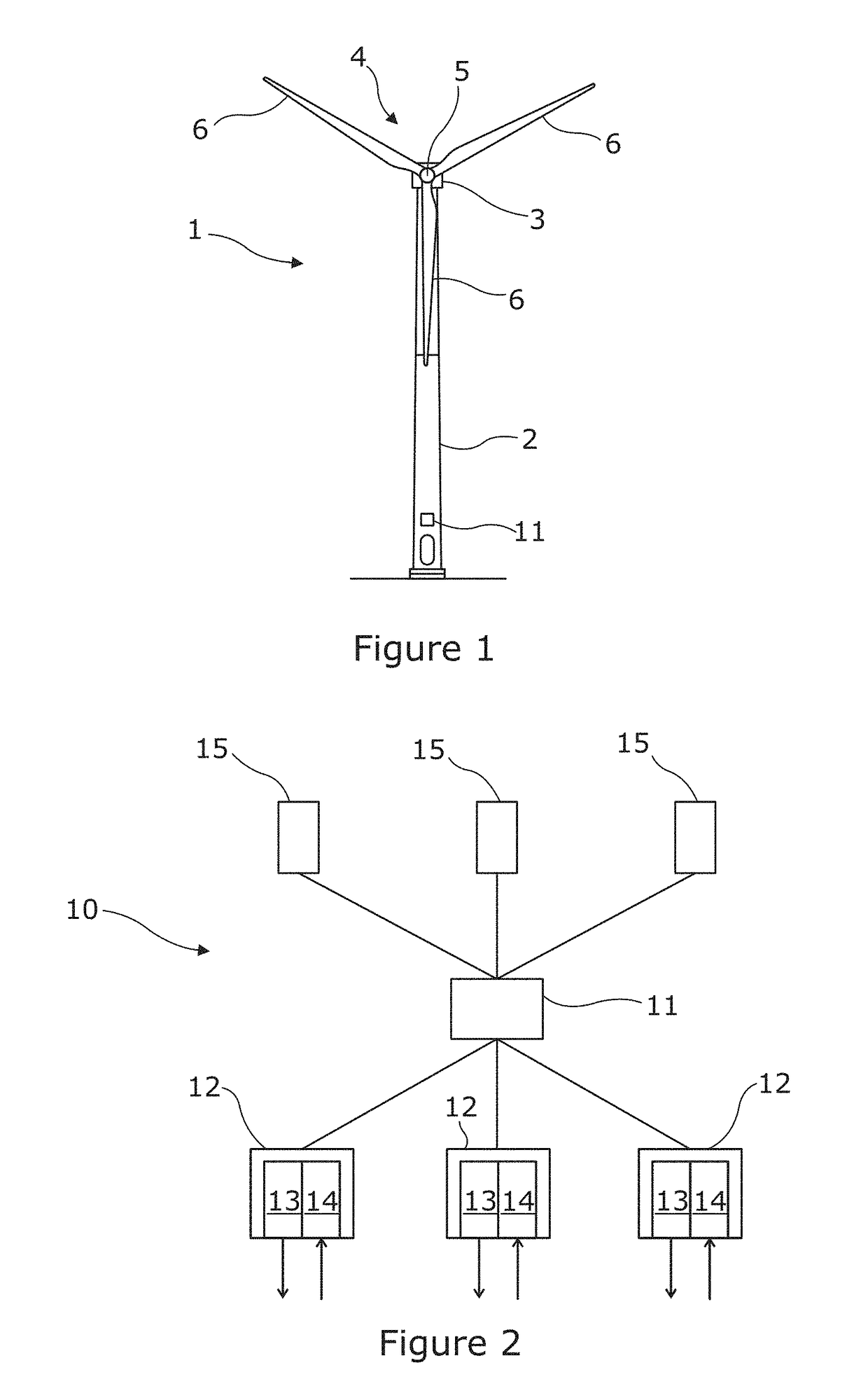
[0046]The wind turbine 1 is provided with a control system 10 according to an embodiment of the present invention that is configured to monitor each of the blades 6 and to control operation of the ...


PUM


Abstract

The present disclosure relates to a control system for a wind turbine that is configured to: obtain a 3-dimensional image of at least a portion of a wind turbine blade; recognise a target feature of the wind turbine blade in the obtained image and identify the position of the target feature; and monitor the state of the wind turbine blade and / or control operation of at least one blade in dependence on the identified position of the feature.

Description

TECHNICAL FIELD[0001]The present disclosure relates to a control system for a wind turbine, to a wind turbine, and to a method of controlling a wind turbine.BACKGROUND[0002]Wind turbines are generally provided with a monitoring system for determining various in use blade state parameters, such as blade deflection, blade twist, blade pitch angle, blade loading, blade vibration and rotational speed. Conventional blade monitoring systems typically include a large number of individual sensors such as strain sensors and accelerometers at various locations in each wind turbine blade. Each sensor is configured to measure a specific quantity at its specific location, and the monitoring system is configured to determine blade state parameters in dependence on data received from each of the sensors.[0003]However, installing a large number of individual sensors in a wind turbine blade is time consuming and expensive, and it may not be possible to install sensors in all locations for which a re...

Claims


Application Information

Patent Timeline
Patent Type & Authority Applications(United States)
IPC IPC(8): F03D7/04F03D7/02G06T17/00
CPCF03D7/045F03D7/0224G06T17/00F05B2270/328F05B2270/101F03D7/02F05B2270/8042F03D17/00Y02E10/72
Inventor GRUNNET, JACOB DELEURANTHYBO, CLAUSNIELSEN, JOHNNYRASMUSSEN, JES
Owner VESTAS WIND SYST AS
Why Eureka
Try Eureka