Method and system for transforming spectral images

a technology of spectral images and transforming methods, applied in the field of image processing, can solve the problems of costly and/or time-consuming transmission

Inactive Publication Date: 2018-06-21
VLAAMSE INSTELLING VOOR TECHNOLOGISCH ONDERZOEK NV VITO
View PDF10 Cites 2 Cited by
  • Summary
  • Abstract
  • Description
  • Claims
  • Application Information

AI Technical Summary

Benefits of technology

[0017]It is an advantage of this embodiment that the normalization can be performed per block of pixels, wherein a block typically represents a rectangular strip of the sensor or a combination of multiple rectangular areas.

Problems solved by technology

A significant challenge that presents itself in connection with the use of filter-based multispectral sensors, is the geometric referencing and registration of the acquired multispectral images.
Such transmissions may be costly and / or time consuming.

Method used


Image

  • Method and system for transforming spectral images
  • Method and system for transforming spectral images
  • Method and system for transforming spectral images

Examples


Embodiment Construction

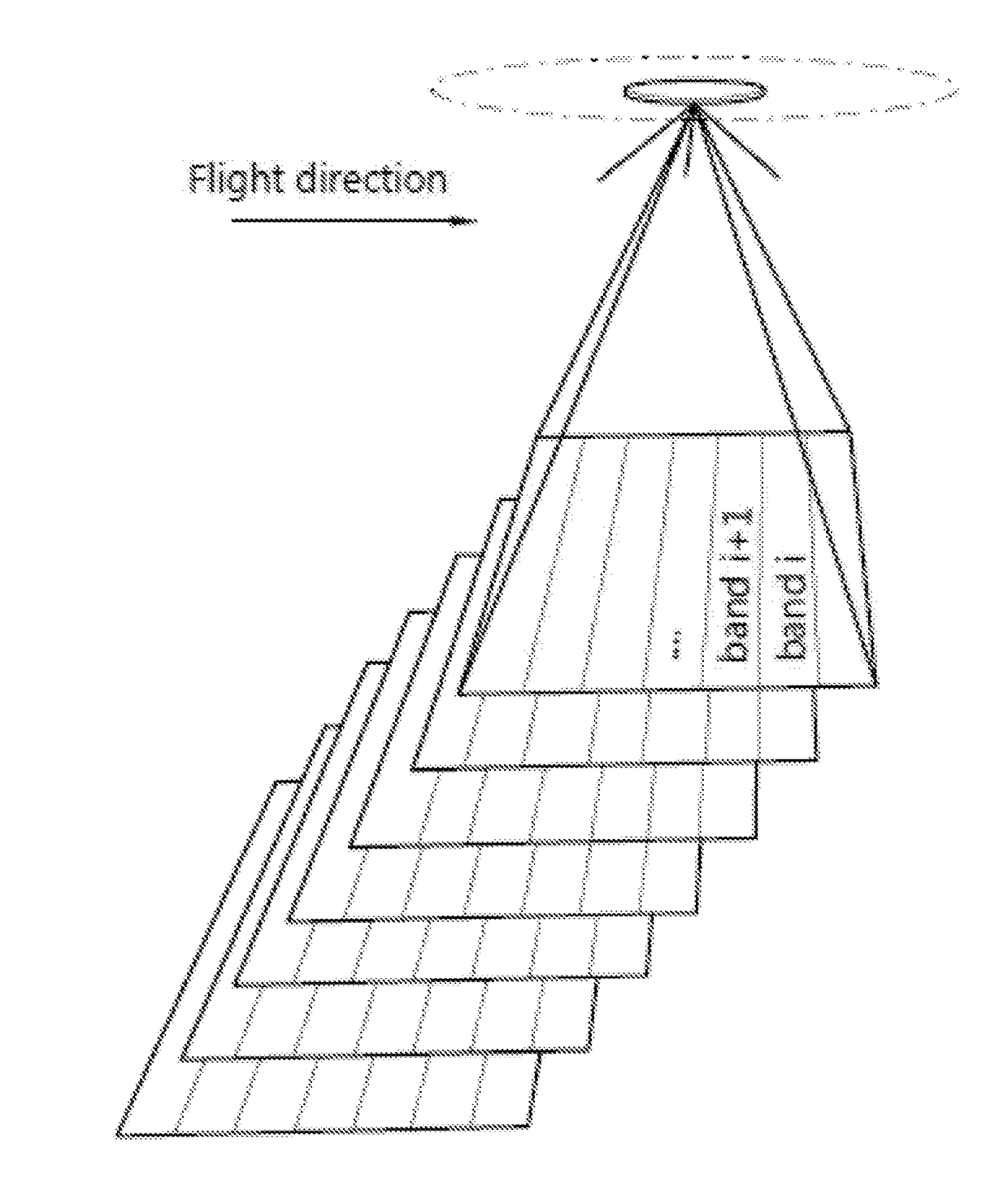
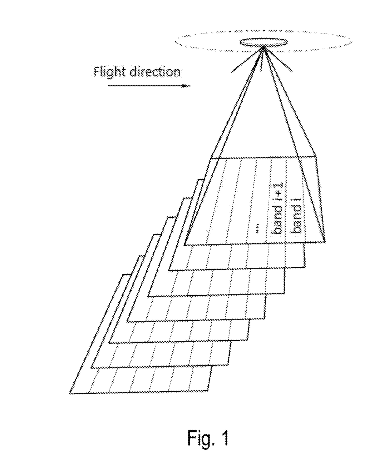
[0029]FIG. 1 provides a perspective view of the region imaged by consecutive acquisitions of a multi-spectral sensor, in particular a hyperspectral sensor. An example of a hyperspectral sensor is disclosed in the aforementioned international patent application publication WO 2011 / 073430 A1, in the name of the present applicant, where it is described as the “first sensor”, operating in conjunction with a second (visual-range) sensor. While the “first sensor” of WO 2011 / 073430 A1 shall be referred to in order to clarify the present invention, it must be understood that the present invention is not limited thereto.

[0030]It is typical of such hyperspectral sensors that different parts of the sensing element are sensitive to different wavelengths. This effect may be obtained by providing a sensing element with a filtering layer that has a wavelength response that varies across the surface of the sensing element. Accordingly, each image taken by such a hyperspectral sensor is in fact a mo...


PUM


Abstract

A method for transforming a set of spectral images, the method including: dividing the images in the set in identically arranged areas; for each of the areas, calculating a predetermined characteristic across the set of images; and, for each of the images, normalizing intensity values in each of the areas in function of the predetermined characteristic of the area. Additionally, a corresponding computer program product and a corresponding image processing system.

Description

FIELD OF THE INVENTION[0001]The invention relates to the field of image processing, e.g. to be applied to images acquired in aerial imaging. More particularly, the present invention relates to a method and a system for transforming spectral images.BACKGROUND[0002]In the field of multispectral and hyperspectral imaging, an alternative to the traditional “pushbroom” method of image acquisition has recently been proposed. The alternative consists of using a two-dimensional sensor provided with a thin-film spectral filter that renders different parts of the sensor sensitive to different wavelengths. The variation of the transmitted wavelength is typically gradual or stepwise along the direction in which the sensor is moved across the scenery (i.e., the direction of flight in the case of an aircraft or spacecraft mounted sensor arrangement). Accordingly, each image taken by such a sensor is in fact a mosaic in which different parts of the image represent the corresponding part of the ter...

Claims


Application Information

Patent Timeline
Patent Type & Authority Applications(United States)
IPC IPC(8): G01J3/28G01J3/36G06K9/42G06K9/00G06V10/32G06V20/13
CPCG01J3/2823G01J3/36G06K9/42G06K9/0063G01J2003/2826G06T2207/10036G01J3/26G01J3/28G06T5/009G06T2207/30181G06V20/194G06V20/13G06V10/32
Inventor LIVENS, STEFANDELAURE, BAVO
Owner VLAAMSE INSTELLING VOOR TECHNOLOGISCH ONDERZOEK NV VITO
Why Eureka
Try Eureka