Wearable display

a wearable display and display technology, applied in the field of wearable displays, can solve the problems of not being able to see through and/or expensive, not being able to meet the needs of viewers, and not being able to wear glasses, etc., to achieve the effect of reducing chroma-aberration, improving cosmetic appearance, and reducing chroma-aberration

Inactive Publication Date: 2018-06-21
ISHII FUSAO
View PDF1 Cites 19 Cited by
  • Summary
  • Abstract
  • Description
  • Claims
  • Application Information

AI Technical Summary

Benefits of technology

[0011]Another aspect of this invention is to provide a system of electronic visual control to adjust focal length for viewer's eye such as near sighted, far sighted and senior vision rather than mechanical focal length adjustment system which will prohibit a stealth display as well as improving cosmetic appearance.
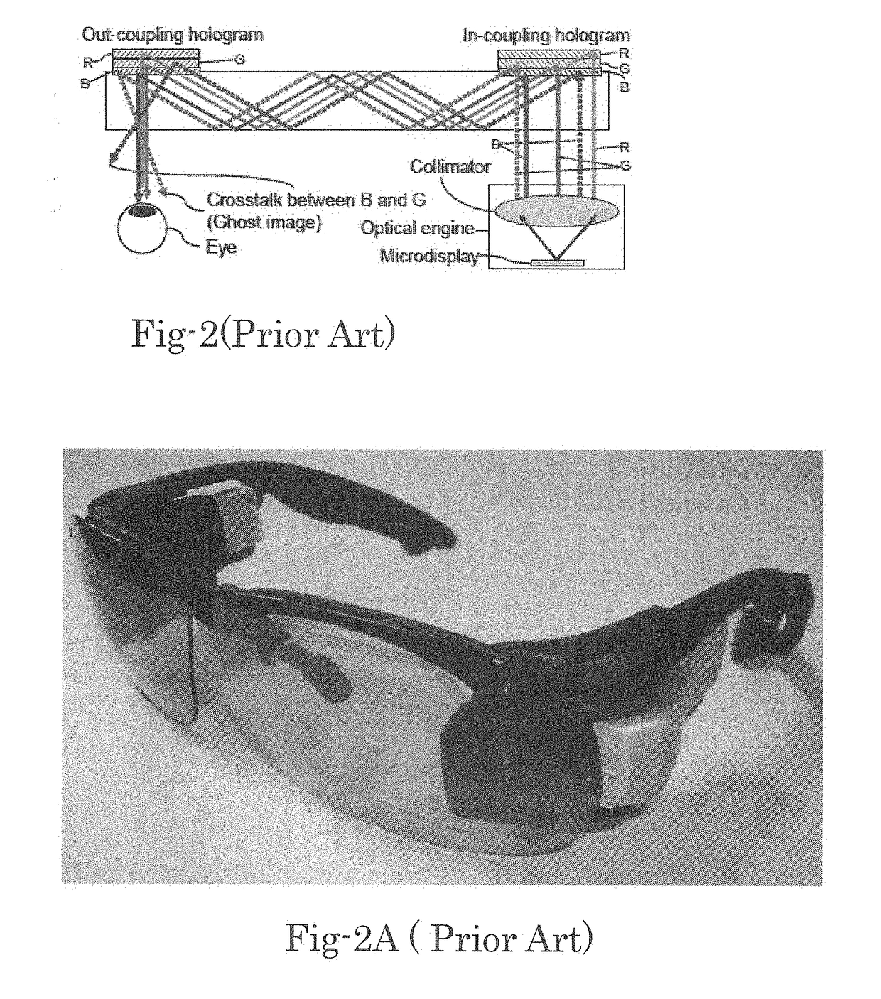
[0012]Another aspect of this invention is to provide an optical system to reduce chroma-aberration and cross talk of colors which the prior arts suffered very badly. The chroma-aberration and color cross talk are very large because of wide band width of LED light source. These problems will be resolved if a laser light source is used because of its very narrow band width of

Problems solved by technology

There are tremendous needs for wearable displays.
However in the past, near eye displays such as Head Mount Display, Head Up Display and Eye Glass Type Display not necessarily satisfied viewers, because they were often too heavy, too large, too dark, low resolution, not see through and/or expensive.
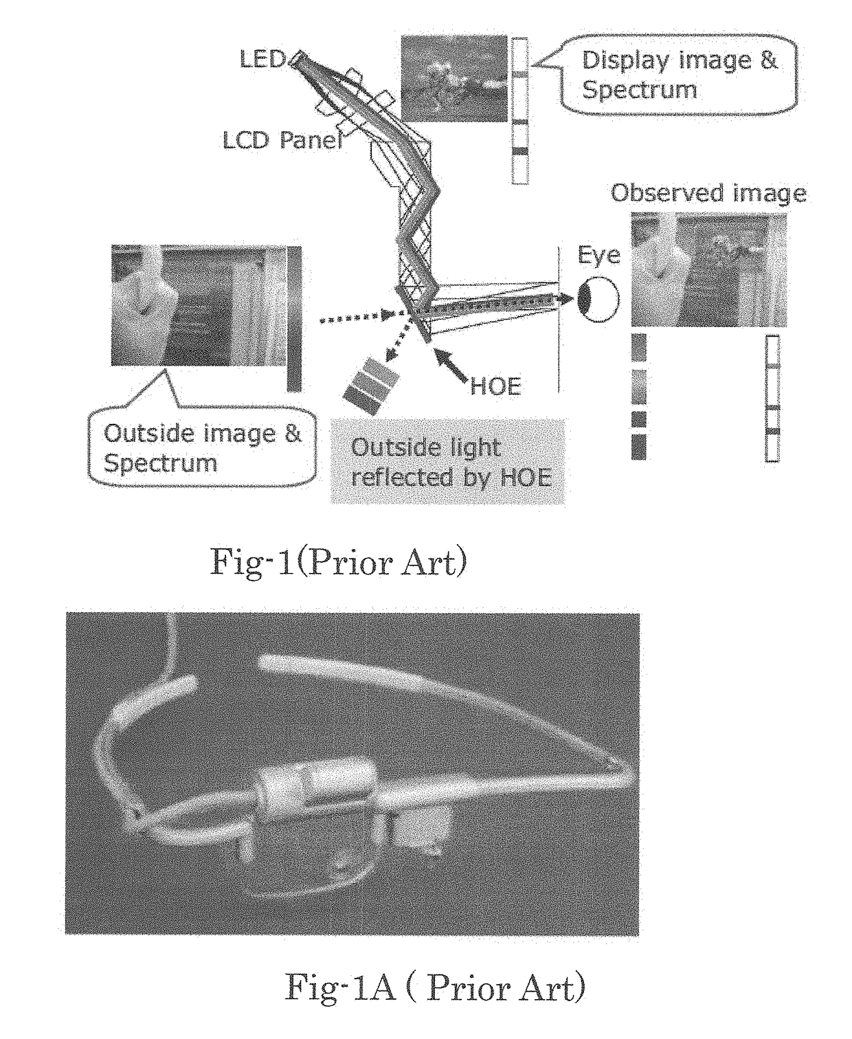
The above three types of displays are using either holographic optical element (HOE) or diffractive optical element (DOE) and all of these have some fundamental

Method used


Image

  • Wearable display
  • Wearable display
  • Wearable display

Examples


Embodiment Construction

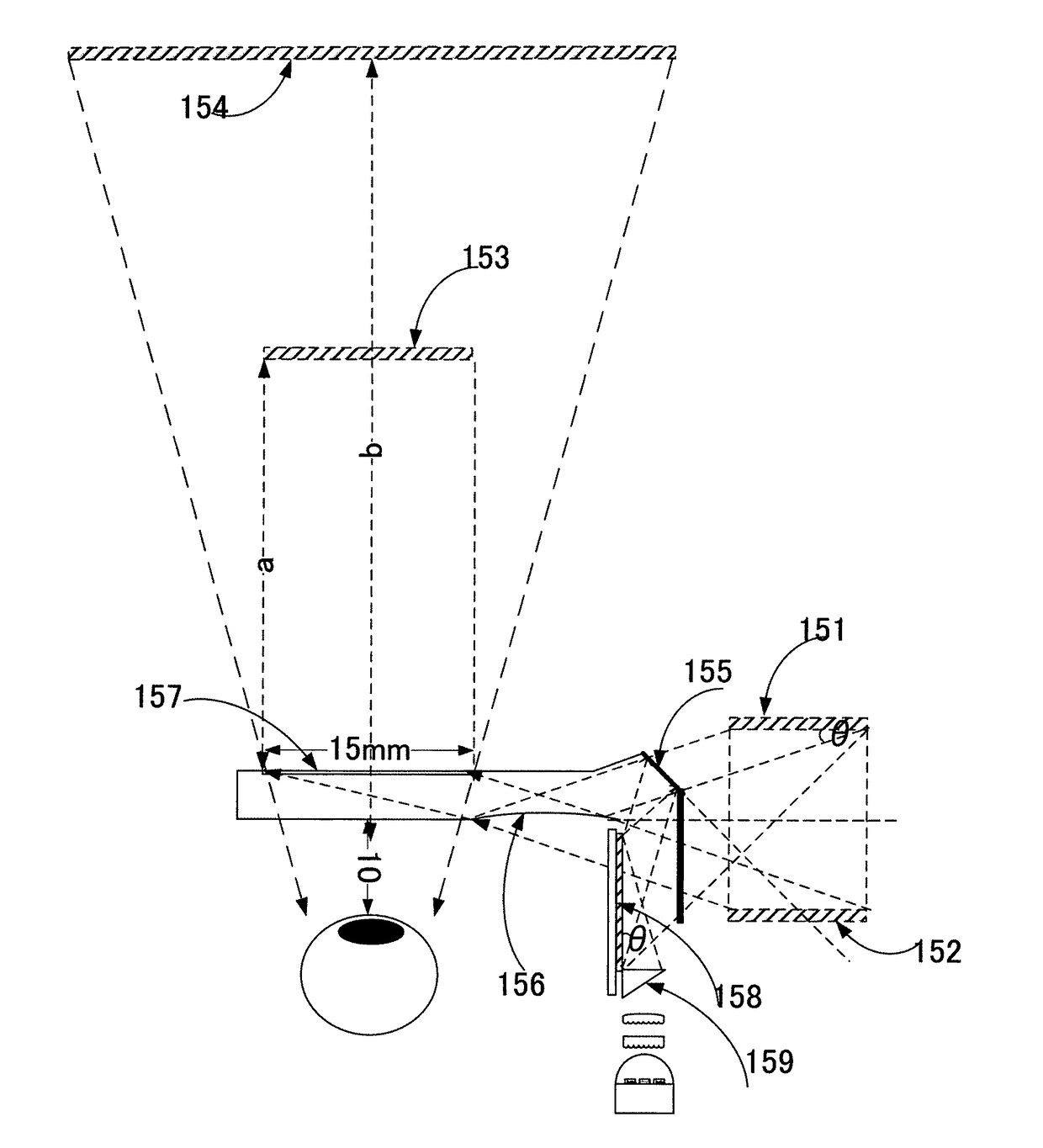
[0083]FIG. 5 shows an exemplary embodiment of this invention. A display device 108 is configured by combining a TIR (total internal reflection) 114 with an array of micromirrors 106. The light sources 116 are provided either as a light emitting diode (LED) or as a laser light source. The light source 116 projects lights to an integrator 101 for integrating three light beams and collimated by a collimation lens 117 to project substantially parallel beams. The light beam from the light source 116 is directed to the array of micromirrors 106. The lights are reflected along a light path 112 when the micromirrors are controlled at an ON state or alone light path 113 when the micromirrors are turned to an OFF state according to the incoming video signals. Solid state light sources 116 emit multi-color light beams and the beams are integrated into substantially a single beam by the integrator 101 and focused by a collimation lens 117 and projected to TIR (total internal reflection) prism 1...


PUM


Abstract

An image display system including tangential outgoing projected light combined with holographic optical element is disclosed. This invention enables very small compact wearable display suitable eyewear display with complete stealth characteristic, electronic vision control and very high solution having large FOV and Eye Box.

Description

CROSS REFERENCE TO RELATED APPLICATIONS[0001]This application is a Non-Provisional application and claims the Priority Dates of previously filed Provisional Applications 61 / 957,258 filed on Jun. 27, 2013, 61 / 958,491 filed on Jul. 29, 2013, 61 / 959,953 filed on Sep. 7, 2013, 61 / 966,519 filed on Feb. 25, 2014 and 61 / 995,664 on filed on Apr. 17, 2014.TECHNICAL FIELD[0002]This invention relates to a display system for projecting an image with a spatial light modulator having outgoing light to a tangential direction and key components enabling super compact wearable display. More particularly, this invention relates to a display suitable for wearable displays with very small form factor.BACKGROUND ART[0003]Wearable displays get attention in recent years after smart phones are well accepted by the market. Wearable display provides hands free operation as well as showing image in the distance same as regular sight. There are tremendous needs for wearable displays. However in the past, near ...

Claims


Application Information

Patent Timeline
IPC IPC(8): G02B26/08G02B27/00G02B5/32G02B27/01G03B21/14G02B27/48G09G3/34
CPCG02B26/0841G02B27/0037G02B5/32G02B27/0018G02B27/0172G02B2027/012G02B27/0068G02B27/48G09G3/346G02B2027/0174G02B2027/011G03B21/147G02B2027/0178G03H2222/18G03H2001/0439
Inventor ISHII, FUSAO
Owner ISHII FUSAO
Why Eureka
Try Eureka