Interface expansion device for a network device

a network device and expansion device technology, applied in the field of interface expansion devices for network devices, can solve problems such as disconnection and other problems

Active Publication Date: 2018-06-21
SIEMENS AG
View PDF3 Cites 0 Cited by
  • Summary
  • Abstract
  • Description
  • Claims
  • Application Information

AI Technical Summary

Benefits of technology

[0019]Switching a data output of the expansion module leads to a change in the sum of the current flowing, with the result t

Problems solved by technology

The disconnection also occurs, for example,

Method used


Image

  • Interface expansion device for a network device
  • Interface expansion device for a network device
  • Interface expansion device for a network device

Examples


Embodiment Construction

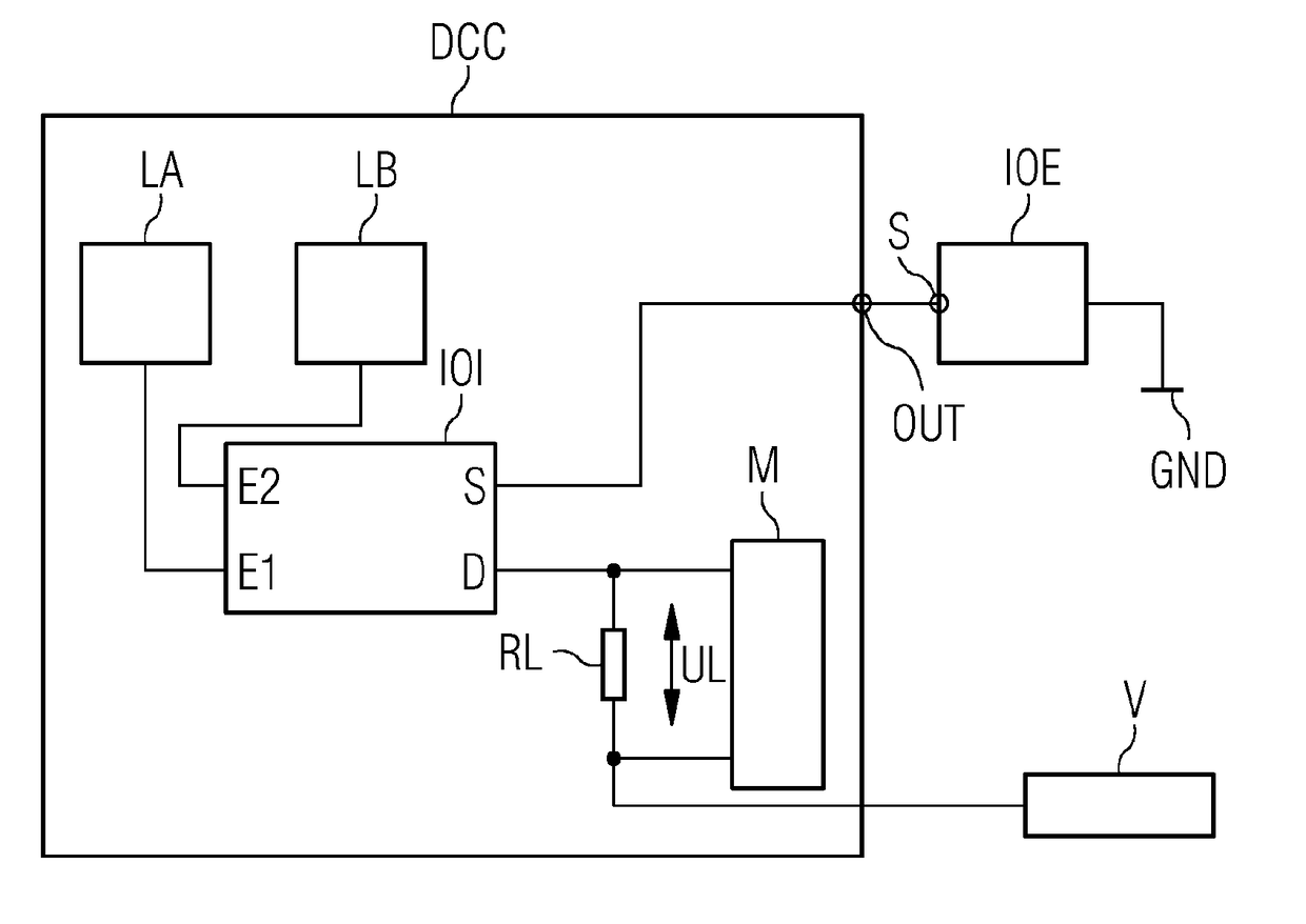
[0029]FIG. 1 depicts an embodiment of an interface expansion device. In the embodiment, a network device DCC, also known as a duplex controller, includes control devices (not illustrated) operating in parallel, e.g. microprocessors operating in parallel or microprocessor cores of a multi-core processor operating in parallel, on which redundant data processing is performed on two isolated execution lanes LA, LB.

[0030]A first execution lane LA is at least temporarily connected to a first control input E1 (Enable) of a network-device-internal interface modular unit IOI. A second execution lane LB is at least temporarily connected to a second control input E2 of the network-device-internal interface modular unit IOI.

[0031]Only one load connection terminal pair S, D is depicted for the interface modular unit IOI, where a first load connection terminal S is conducted to the outside as a digital data output OUT of the network device DCC. The first load connection terminal S corresponds, fo...


PUM


Abstract

The claimed interface extension device is based on a network device (DCC) having at least one previously unoccupied digital data output (OUT), to which an interface extension module (IOE) having at least one supply voltage input (S) and having a plurality of digital interfaces is coupled in the claimed manner. In this way, the supply voltage input (S) of the interface extension module (IOE) is interconnected with the digital data output (OUT) of the network device (DCC), so that in event of an error, the interface extension module (IOE) and all the digital interfaces thereof can be switched off. In addition, by measuring the sum current flowing through the outputs of the interface extension module, the load diagnosis capacity of the network configuration can be extended to the interface extension device. The claimed interconnection of the supply voltage input (S) of the interface extension module with the digital data output (OUT) of the network configuration has the advantage of also implementing a fail-safe behavior for conventional interface extension modules.

Description

CROSS REFERENCE TO RELATED APPLICATIONS[0001]The present patent document is a § 371 nationalization of PCT Application Serial Number PCT / EP2016 / 061288, filed May 19, 2016, designating the United States, which is hereby incorporated by reference in its entirety. This patent document also claims the benefit of DE 102015211478.3, filed on Jun. 22, 2015, which is also hereby incorporated by reference in its entirety.FIELD[0002]Embodiments relate to an interface expansion device for a network device.BACKGROUND[0003]In safety-relevant networks, such as in automation installations or in the automotive vehicle sector, for example, safety-relevant data is transmitted even in the case of faults in hardware components or transmission paths. In safety-relevant networks, the operation of a plurality of network devices connected in a ring-shaped topology is known.[0004]A further measure for increasing safety is provided by redundant data processing within a network device. A network device, also ...

Claims


Application Information

Patent Timeline
IPC IPC(8): H04L12/40H04L12/10G01R19/00G06F9/38
CPCH04L12/40032H04L12/10G01R19/0092H04L12/40176G06F9/3885H04L12/40045H04L12/40169
Inventor ARMBRUSTER, MICHAELZIRKLER, ANDREAS
Owner SIEMENS AG
Why Eureka
Try Eureka