Eureka AIR delivers breakthrough ideas for toughest innovation challenges, trusted by R&D personnel around the world.

Vehicle travel control device

Active Publication Date: 2018-06-28
TOYOTA JIDOSHA KK
View PDF19 Cites 3 Cited by
  • Summary
  • Abstract
  • Description
  • Claims
  • Application Information

AI Technical Summary

Benefits of technology

The present disclosure provides a technique for improving acceleration performance when there is a difference in driving force between left and right wheels. The load distribution control is performed by activating the first and second active stabilizers in opposite directions to lift up either the high-κ or low-κ side, depending on the difference in driving force between left and right wheels. This results in an increase in the total actual driving force and improved acceleration performance.

Problems solved by technology

However, even when the turning control is performed, the driving force is not increased and thus acceleration performance is not increased.

Method used


Image

  • Vehicle travel control device
  • Vehicle travel control device
  • Vehicle travel control device

Examples


Embodiment Construction

[0074]Embodiments of the present disclosure will be described below with reference to the attached drawings.

1. Outline

1-1. Load Distribution Control

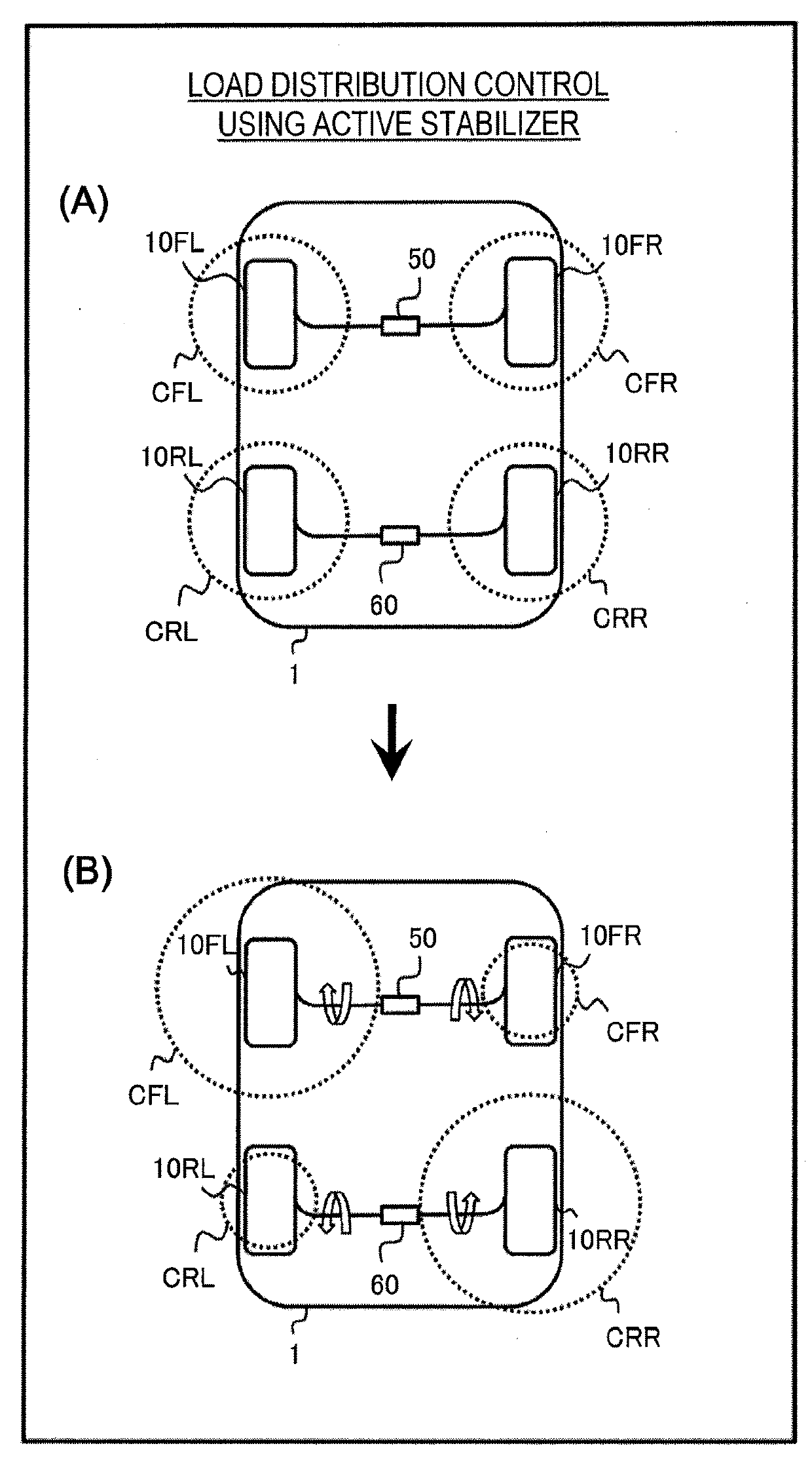
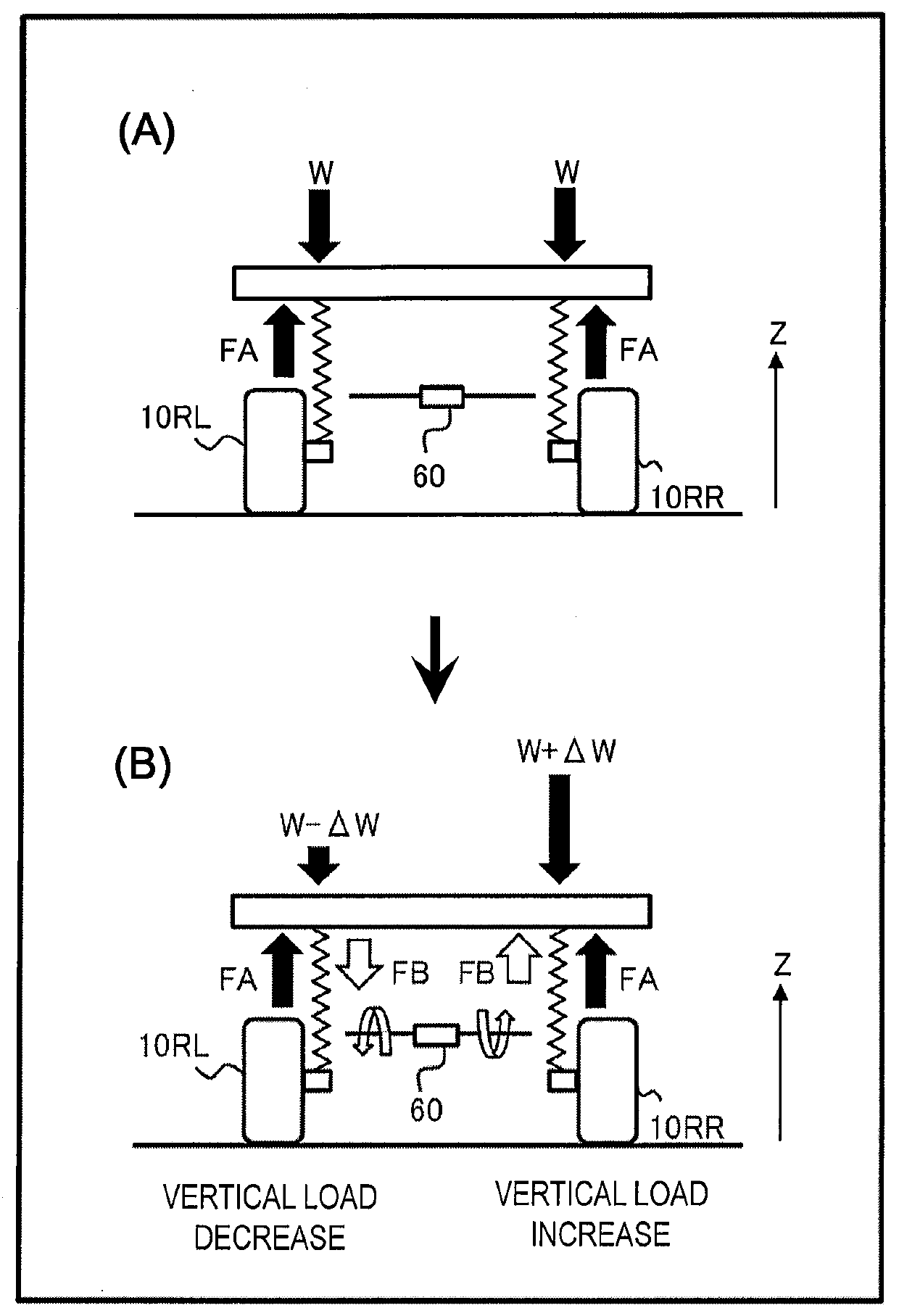
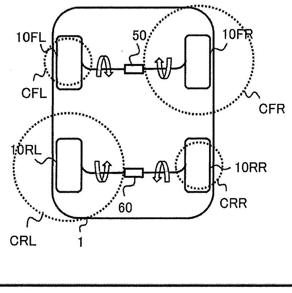
[0075]Let us first explain “load distribution control” serving as a basis for the present embodiment. Here, the load distribution control is to actively control a vertical load on each wheel of a vehicle.

[0076]FIG. 1 is a conceptual diagram for explaining the load distribution control according to the present embodiment. The vehicle 1 is provided with a left front wheel 10FL, a right front wheel 10FR, a left rear wheel 10RL, and a right rear wheel 10RR. In the following description, the left front wheel 10FL and the right front wheel 10FR may be collectively referred to as a “front wheel”, and the left rear wheel 11RL and the right rear wheel 10RR may be collectively referred to as a “rear wheel”. The left front wheel 10FL and the left rear wheel 10RL may be collectively referred to as a “left wheel”, and the right front wheel 10FR and t...


PUM


Abstract

A first active stabilizer is installed on a main drive wheel side, and a second active stabilizer is installed on a subordinate drive wheel side. A control device performs load distribution control when a difference in actual driving force between left and right sides of a vehicle exceeds a threshold value during acceleration. A high-μ side is one of the left and right sides with a greater actual driving force, and a low-μ side is another of the left and right sides. The load distribution control includes a first mode performed when a vehicle speed is equal to or lower than a first reference value. In the first mode, the control device actuates the first active stabilizer in a direction to lift up the high-μ side and actuates the second active stabilizer in a direction to lift up the low-μ side.

Description

BACKGROUNDTechnical Field[0001]The present disclosure relates to vehicle travel control when a difference in driving force between left and right wheels occurs during acceleration of a vehicle.Background Art[0002]During braking or acceleration on a split-μ road, a yaw moment is generated in a vehicle due to a difference in braking force or driving force between left and right wheels. Patent Literature 1 discloses a technique that detects such the yaw moment and performs turning control to counteract the detected yaw moment. Patent Literature 2 discloses a technique that detects a yaw moment generated during braking on a split-μ road and performs turning control to counteract the detected yaw moment.[0003]Patent Literature 3 discloses an active stabilizer for suppressing a roll behavior during cornering.LIST OF RELATED ART[0004]Patent Literature 1: Japanese Laid-Open Patent Publication No. 2005-349914[0005]Patent Literature 2: Japanese Laid-Open Patent Publication No. 2010-195089[000...

Claims


Application Information

Patent Timeline
IPC IPC(8): B60G17/016B60G17/0165B60G21/055
CPCB60G17/0164B60G17/0165B60G21/0555B60G2400/822B60G2400/106B60G2400/204B60G2800/214B60G2800/012B60G2400/61B60G2800/016B60G2202/42B60G2202/442B60W10/06B60W10/18B60W10/20B60W10/22B60W30/025B60W2710/06B60W2710/20B60W2710/22B60W2710/18B60W2520/00B60W2520/105B60W2520/10B60W2520/125B60W2520/28
Inventor FUJITA, YOSHITAKA
Owner TOYOTA JIDOSHA KK
Why Eureka
Eureka Blog
Learn More