Eureka AIR delivers breakthrough ideas for toughest innovation challenges, trusted by R&D personnel around the world.

Camera module and camera apparatus comprising same

Pending Publication Date: 2022-06-02
LG INNOTEK CO LTD
View PDF0 Cites 0 Cited by
  • Summary
  • Abstract
  • Description
  • Claims
  • Application Information

AI Technical Summary

Benefits of technology

The camera actuator and camera module described in this patent reduce friction torque during zooming, which improves the driving force, reduces power consumption, and improves control characteristics. This prevents image quality or resolution issues caused by lens decenter or tilt during zooming. The first guide part includes a first-first rail and a first-second rail that guide the first lens assembly, improving accuracy of alignment. The center of a protrusion of the first guide part and the center of a groove of the third housing are eccentrically disposed to increase the accuracy of lens alignment between a plurality of lens groups, minimizing decenter and lens tilt during zooming.

Problems solved by technology

Meanwhile, a zoom actuator is used for a zooming function of a camera module, but frictional torque is generated when a lens is moved by mechanical movement of the actuator, and there are technical problems such as a decrease in driving force, an increase in power consumption, or a deterioration in control characteristics due to the friction torque.
Specifically, in order to achieve the best optical characteristics by using a plurality of zoom lens groups in a camera module, an alignment between the plurality of lens groups and an alignment between the plurality of lens groups and an image sensor should be well matched, but when a decentering in which a spherical center between the lens groups deviates from an optical axis, a tilt which is a phenomenon of lens tilt, or a phenomenon in which central axes of the lens groups and the image sensor are not aligned occurs, an angle of view changes or defocus occurs, which adversely affects image quality or resolution.
Meanwhile, when increasing a separation distance in a region in which friction occurs in order to reduce a friction torque resistance while moving a lens for a zooming function in a camera module, there is a contradiction in technical problems in which a lens decentering or a lens tilt are deepened when zoom movement or reversal of the zoom movement is performed.
Therefore, in a darker environment, in a high-pixel camera, image shake due to camera shake that occurs while a shutter speed is slower occurs more seriously.
Recently, an ultra-thin and ultra-small camera module is required in accordance with technological trends, but since the ultra-small camera module has a space limitation for OIS drive, there is a problem that it is difficult to implement the OIS function applied to a general large camera, and there is a problem that the ultra-thin and ultra-small camera module cannot be implemented when the OIS drive is applied.
In addition, in the conventional OIS technology, an OIS driver is disposed at a side surface of a solid-state lens assembly within a limited camera module size, and thus there is a problem that it is difficult to secure a sufficient amount of light because a size of a lens to be subjected to OIS is limited.
Specifically, in order to achieve the best optical characteristics in a camera module, an alignment between the lens groups at the time of OIS implementation should be well matched through movement of a lens or tilting of a module, but in the conventional OIS technology, when a decenter in which a spherical center between the lens groups deviates from an optical axis or a tilt which is a phenomenon of lens tilt occurs, there is a problem that adversely affects image quality or resolution.
In addition, the conventional OIS technology may implement AF or Zoom at the same time as OIS driving, but an OIS magnet and an AF or Zoom magnet are disposed close to each other due to space limitation of a camera module and a position of a driving part of the conventional OIS technology, and cause a magnetic field interference, and thus there is a problem that the OIS driving is not performed normally, and a decent or a tilt phenomenon is induced.
Further, in the conventional OIS technology, since a mechanical driving device is required for moving the lens or tilting the module, there is a problem that a structure is complicated and power consumption is increased.

Method used


Image

  • Camera module and camera apparatus comprising same
  • Camera module and camera apparatus comprising same
  • Camera module and camera apparatus comprising same

Examples


embodiment

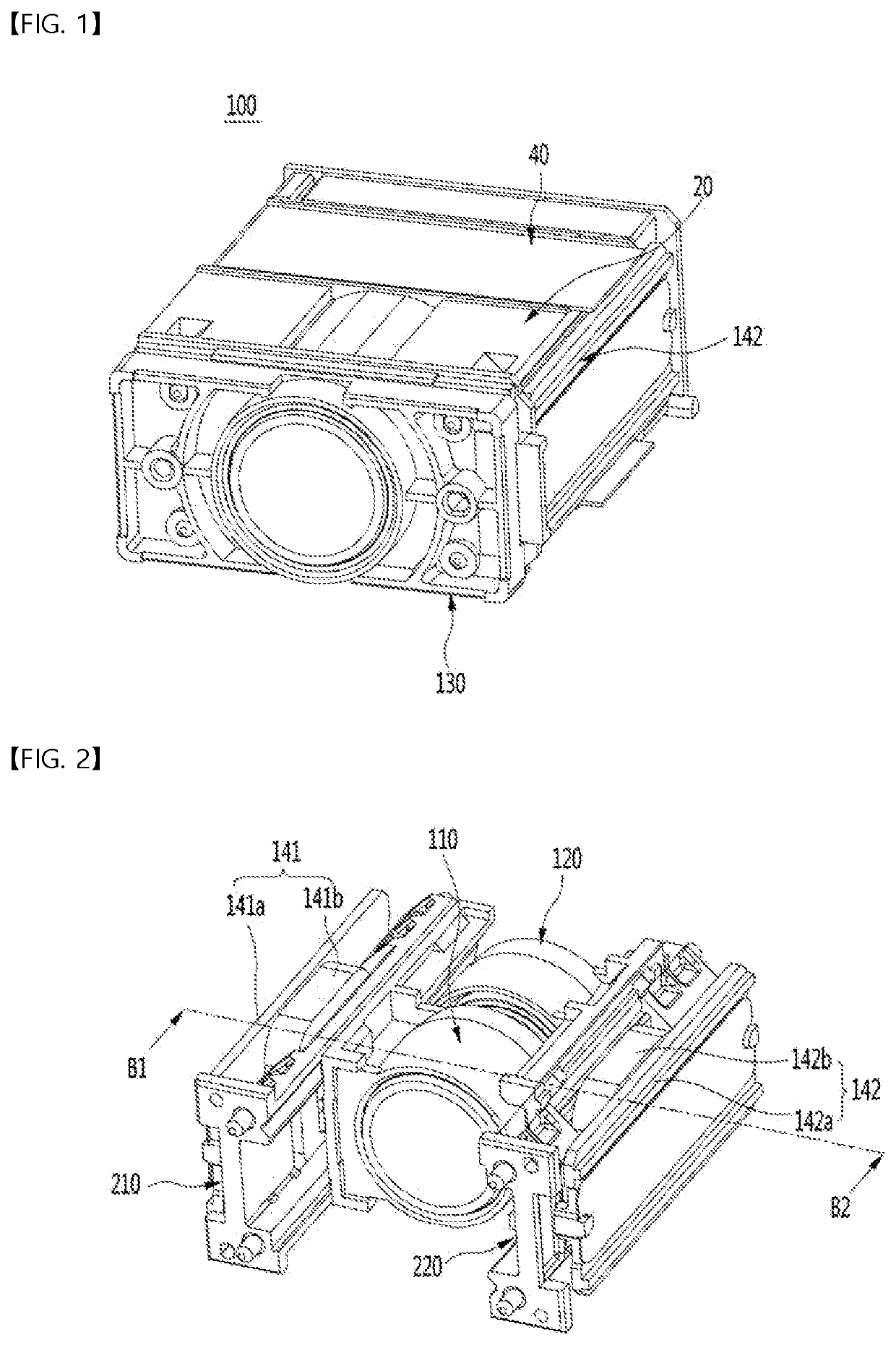
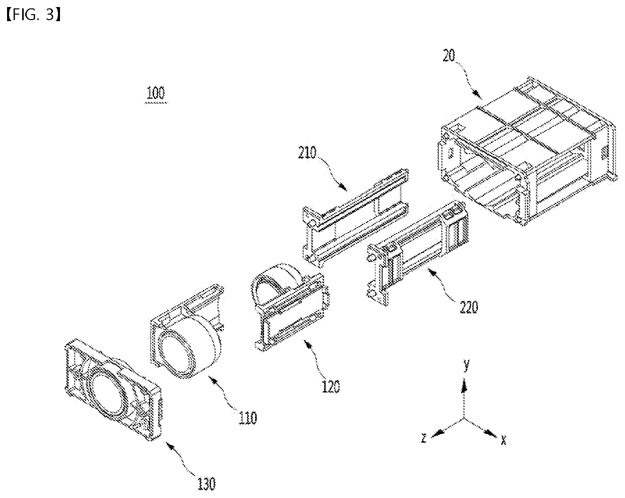
[0134]FIG. 1 is a perspective view of a camera module 100 according to an embodiment, FIG. 2 is a perspective view in which a part of the configuration of the camera module according to the embodiment shown in FIG. 1 is omitted, and FIG. 3 is an exploded perspective view in which a part of the configuration of the camera module according to the embodiment shown in FIG. 1 is omitted.

[0135]Referring to FIG. 1, the camera module 100 according to the embodiment may include a base 20, a circuit board 40 disposed outside the base 20, a fourth driving part 142, and a third lens assembly 130.

[0136]FIG. 2 is a perspective view in which the base 20 and the circuit board 40 are omitted in FIG. 1, and referring to FIG. 2, a camera module 100 according to an embodiment includes a first guide part 210, a second guide part 220, a first lens assembly 110, a second lens assembly 120, a third driving part 141, and a fourth driving part 142.

[0137]The third driving part 141 and the fourth driving part ...


PUM


Abstract

A camera module according to an embodiment may include a base including a first side wall and a second side wall corresponding to the first side wall, a first guide part disposed adjacent to the first side wall of the base, a second guide part disposed adjacent to the second side wall of the base, a first lens assembly that moves along the first guide part, a second lens assembly that moves along the second guide part, a first ball disposed between the first guide part and the first lens assembly, and a second ball disposed between the second guide part and the second lens assembly.

Description

TECHNICAL FIELD[0001]An embodiment relates to a camera module and a camera apparatus including the same.BACKGROUND ART[0002]A camera module performs a function of photographing a subject and storing it as an image or a moving image, and is mounted on a mobile terminal such as a mobile phone, a laptop a drone, a vehicle, and the like.[0003]Meanwhile, an ultra-small camera module is built into a portable device such as a smartphone, a tablet PC, and a notebook, and such a camera module may perform an autofocus (AF) function adjusting automatically a distance between an image sensor and a lens to adjust a focal length of the lens.[0004]In addition, recently, a camera module may perform a zooming function of zooming up or zooming out photographing a subject by increasing or decreasing a magnification of a long-distance subject through a zoom lens.[0005]Further, recently, a camera module adopts an image stabilization (IS) technology to correct or prevent image shake caused by camera move...

Claims


Application Information

Patent Timeline
IPC IPC(8): G02B7/10G02B7/02G02B27/64G03B5/00G03B13/36
CPCG02B7/102G02B7/021G03B2205/0007G03B5/00G03B13/36G02B27/646G02B3/14G02B5/06G03B30/00G03B3/10G03B2205/0053G03B17/02G03B2205/0046
Inventor ROH, HYUN GYUKIM, CHANG YEON
Owner LG INNOTEK CO LTD
Why Eureka
Eureka Blog
Learn More