Apparatus and method for detecting piping alignment using image information and laser sensor

a technology of laser sensor and image information, which is applied in the direction of mechanical apparatus, using reradiation, instruments, etc., can solve the problems of limited size and type, difficult to carry out alignment work, and piping manual work by operators, so as to reduce the defect rate, accurate alignment values, and efficient measurement of the alignment of pipes

Active Publication Date: 2018-06-28
MOKPO NAT MARITIME UNIV IND ACADEMIC COOPERATION FOUND
View PDF0 Cites 6 Cited by
  • Summary
  • Abstract
  • Description
  • Claims
  • Application Information

AI Technical Summary

Benefits of technology

[0017]In accordance with the apparatus and the method for detecting a piping alignment using image information and a laser sensor according to an embodiment of the present invention, it is possible to perform the alignment work of the pipes by applying the structure of the fixed plate and the movable plate, and efficiently measure the alignment of the pipes by rotating the laser sensor and the imaging apparatus which are rotated along the ring-type stage, as well as obtain accurate alignment values by analyzing an image acquired from the imaging apparatus.
[0018]In addition, according to the present invention, the alignment apparatus used for performing a welding operation of the pipes and beams may automatically align the pipes, thereby reducing a defect rate and improving working efficiency during the welding.
[0019]Further, since many pipes mounted on a ship have substantially large size and weight, when using a manual alignment apparatus, an operation time is increased and an accuracy of the alignment process is deteriorated. However, according to the present invention, by using the automatic pipe alignment apparatus, it is possible to reduce the operation time and improve the accuracy thereof.
[0020]Furthermore, according to the present invention, fluid machine and system makers, and piping makers other than related to the shipping industry, often have a poor working environment in a small scale, and when the automatic alignment apparatus is used by such makers, it is possible to improve an enterprise competitiveness due to a decrease in production costs resulting from a reduction in the entire production time, and an increase in the durability of the products.

Problems solved by technology

Currently, such a piping has a lot of difficulties for manual work by an operator due to a load and a volume thereof in a case of small, medium and large pipings.
However, when installing a large-sized rail in a workplace, it is difficult to carry out the alignment work such as a pipe having various sizes and types due to a disadvantage of occupying a lot of work space and the uniformly determined rails.
Furthermore, when using a jig, or the like, there is a limitation on the size and type of the target pipe, and even when using a clamping mechanism, it is necessary to acquire proficiency, and it takes a lot of time to perform the alignment work, as well as it is difficult to correctly detect and ascertain the alignment.

Method used


Image

  • Apparatus and method for detecting piping alignment using image information and laser sensor
  • Apparatus and method for detecting piping alignment using image information and laser sensor
  • Apparatus and method for detecting piping alignment using image information and laser sensor

Examples


Embodiment Construction

[0026]Hereinafter, exemplary embodiments of the present invention will be described in detail. The following embodiments are described in order to enable those of ordinary skill in the art to embody and practice the present invention. However, the present invention is not limited to the embodiments disclosed below, but can be implemented in various forms. To aid in understanding the present invention, like numbers refer to like elements throughout the description of the drawings, and the description of the same elements will not be described.

[0027]In the specification, when the explanatory phrase a part “includes” a component is used, this means that the part may further include the component without excluding other components, so long as special explanation is not given.

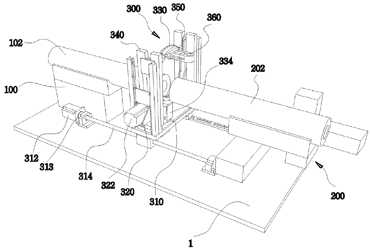
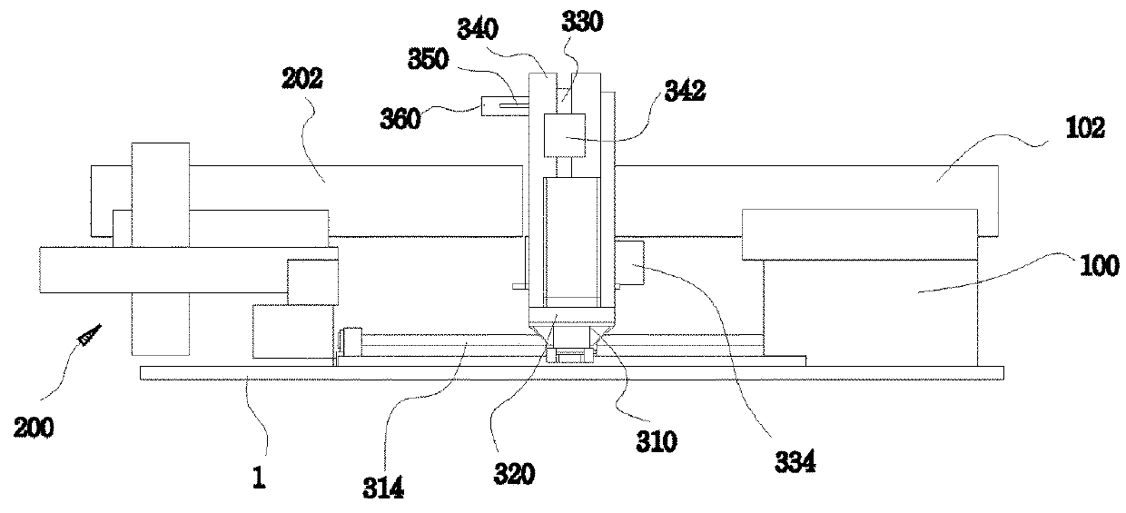
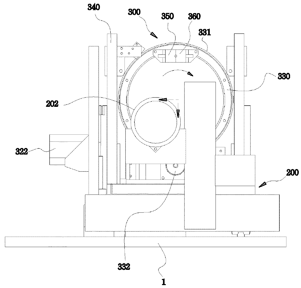
[0028]FIG. 1 is a schematic perspective view of an apparatus for detecting a piping alignment according to an embodiment of the present invention, FIG. 2 is a rear view of the apparatus for detecting a piping alignm...


PUM

PropertyMeasurementUnit
angleaaaaaaaaaa
cutting anglesaaaaaaaaaa
distanceaaaaaaaaaa

Abstract

The present invention provides an apparatus and a method for detecting a piping alignment using image information and laser sensors capable of precisely and accurately measuring and aligning the alignment of the entire pipes. The apparatus includes: a fixed plate installed on a base stage and having a reference pipe located thereon; a movable plate installed on the base stage along three axes to face the reference pipe and has an aligning pipe located thereon; a circular stage installed between the reference and aligning pipes and is configured to rotate and move along three axes so as to detect levelness and deformations of the reference and aligning pipes; a laser sensor and an imaging device installed on an upper side of the circular stage; and a controller configured to control the laser sensor and the imaging device and determine an alignment of the aligning pipe.

Description

CROSS-REFERENCE TO RELATED APPLICATIONS[0001]This application claims priority to Korean Patent Application No. 10-2016-0176662, filed on Dec. 22, 2016 in the Korean Intellectual Property Office, the entire disclosure of which is incorporated herein by reference.BACKGROUND OF THE INVENTION1. Field of the Invention[0002]The present invention relates to an apparatus and a method for detecting a piping alignment using image information and a laser sensor, and more particularly, to an apparatus and a method for detecting a piping alignment using image information and a laser sensor, which may automatically align various medium and large pipes, so as to allow an operator to easily carry out a welding work.2. Description of the Related Art[0003]A lot of pipings are required for various plants and ships. In particular, for the ships, all of seawater, fresh water, lubricants and fuel oil are transported and supplied through the piping. Currently, such a piping has a lot of difficulties for m...

Claims


Application Information

Patent Timeline
Patent Type & Authority Applications(United States)
IPC IPC(8): F16L1/10G01B11/27
CPCG01B11/272F16L1/10F16L13/02G01B11/14G01B11/27G01S17/88G06T7/0004F16L1/235E21B19/16B21D19/00
Inventor NAM, TAEK-KUNKIM, JIN-MANKIM, HEON-HUIKIM, JAE-JUNG
Owner MOKPO NAT MARITIME UNIV IND ACADEMIC COOPERATION FOUND
Why Eureka
Try Eureka