Painting method and device for same

a technology of liquid paint and nozzle, which is applied in the direction of electrostatic spraying apparatus, movable spraying apparatus, coatings, etc., can solve the problems of reducing the centrifugal force that acts on the liquid paint, not easy to form a coating, and difficult to improve the application efficiency, so as to reduce the spread range of liquid paint flying toward the workpiece is narrowed, and the rotational speed of the bell cup is reduced

Inactive Publication Date: 2018-07-05
HONDA MOTOR CO LTD
View PDF9 Cites 4 Cited by
  • Summary
  • Abstract
  • Description
  • Claims
  • Application Information

AI Technical Summary

Benefits of technology

[0016]According to the present invention, as the bell cup, a large-diameter bell cup having a diameter of 75 to 150 mm is used. As a result, even when the rotational speed of the bell cup is reduced, it is possible to obtain a droplet having a diameter approximately equal to that of a droplet in the case of a small-diameter bell cup. This makes it easy to obtain a coating having a desired thickness.
[0017]In addition, with a decrease in the rotational speed of the bell cup, a force by which the liquid paint flies outward in the direction of the diameter of the bell cup becomes smaller. As a result, the spreading range of the liquid paint flying toward the workpiece is narrowed. This makes it easy to apply the liquid paint to a desired area of the workpiece in a concentrated manner. That is, application efficiency is improved.
[0018]For the above-described reasons, it is possible to form a coating having a desired thickness efficiently in a desired area of the workpiece.

Problems solved by technology

As a result, it is not easy to form a coating having a desired thickness in a desired area, which makes it difficult to improve application efficiency.
However, if the rotational speed is excessively reduced, the centrifugal force that acts on the liquid paint is decreased.
As a result, it is not easy to shear the liquid paint and turn it into droplets.
Consequently, particles of the liquid paint become large and it is not easy to control the thickness of a coating.

Method used


Image

  • Painting method and device for same
  • Painting method and device for same
  • Painting method and device for same

Examples


Embodiment Construction

[0031]Hereinafter, regarding a painting method according to the present invention, a preferred embodiment thereof will be described in detail with reference to the attached drawings in connection with a rotary atomization-type painting device for carrying out the printing method.

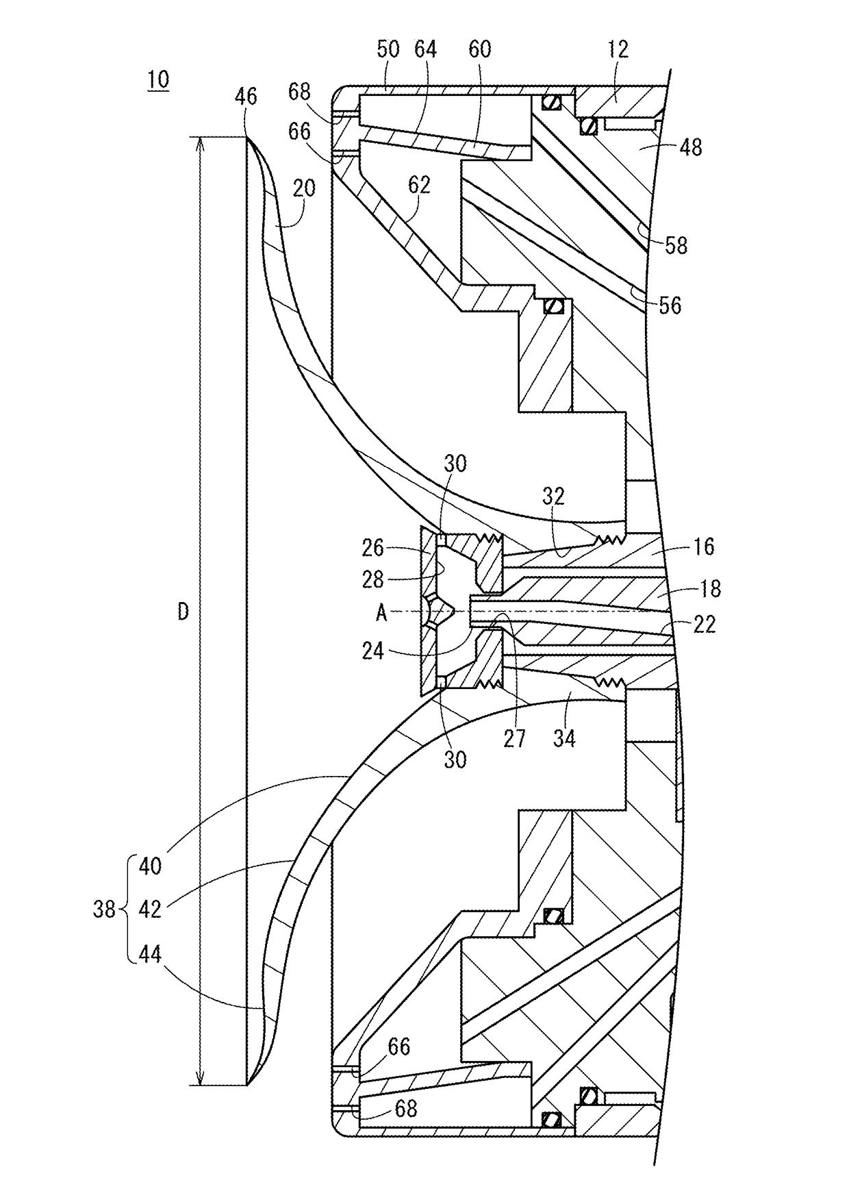
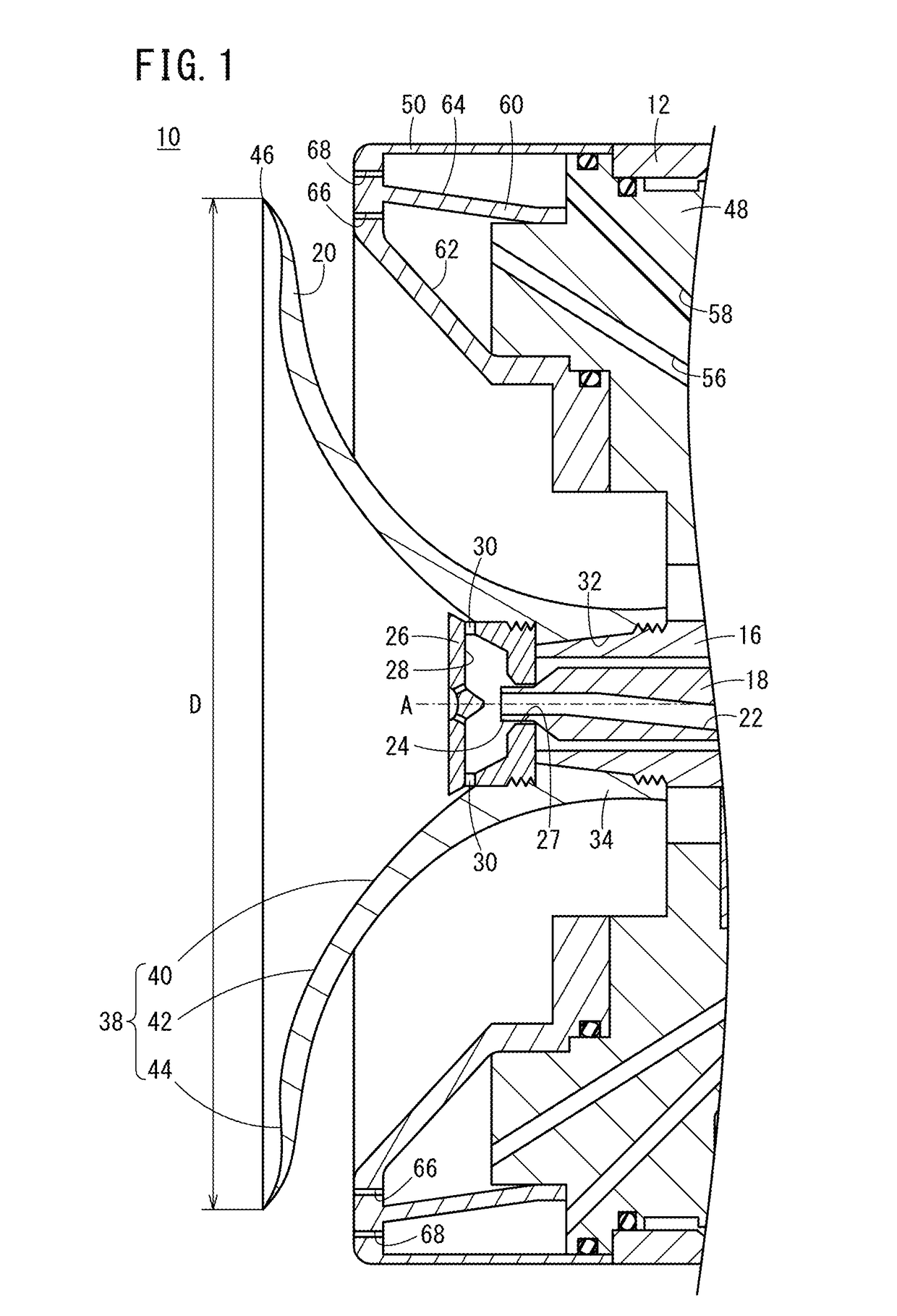
[0032]FIG. 1 is a side cross-sectional view of a rotary atomization-type painting device 10 according to the present embodiment in a longitudinal direction thereof. This rotary atomization-type painting device 10 is provided at the tip of an arm that constitutes a painting robot (both of which are not depicted in the drawing).

[0033]The rotary atomization-type painting device 10 includes an unillustrated air motor provided in a casing 12, a shaft 16 that is rotated at high speed by the air motor, a tube member 18 for letting liquid paint flow therethrough, and a bell-shaped bell cup 20 coupled to the tip of the shaft 16 by threaded engagement between screw portions. To the air motor, compressed air is supplie...


PUM


Abstract

The present invention relates to a painting method and a rotating atomization type painting device. On an inner surface of a bell cup constituting the rotating atomization type painting device are formed a first paint diffusion unit positioned on the inside in the radial direction and a second paint diffusion unit positioned between the first paint diffusion unit and a peripheral edge part. The first paint diffusion unit has a convex shaped curved surface extending toward the center of rotation of the bell cup, whereas the second paint diffusion unit has a concave shaped curved surface extending away from the center of rotation. The diameter of the bell cup is set at 75-150 mm, and the speed of rotation of the bell cup is set at 8000-30000 rpm.

Description

TECHNICAL FIELD[0001]The present invention relates to a painting method and a device therefor, the painting method of spraying paint onto a workpiece from the periphery of an internal surface of a rotatable bell cup.BACKGROUND ART[0002]A rotary atomization-type painting device is widely used as a painting device that paints a body and so forth of an automobile. As is generally known, in the rotary atomization-type painting device, a bell cup that constitutes the rotary atomization-type painting device is rotated with a high voltage being applied thereto, and, in this state, liquid paint (for example, conductive paint) is supplied to the bell cup. The liquid paint is electrified and, as described in Japanese Patent No. 4274894, atomized due to the centrifugal force, and flies out of the periphery of the bell cup as a liquid thread. The flying liquid paint applied to the body by an electrostatic action or the like based on a potential difference. As a result, electrostatic painting is...

Claims


Application Information

Patent Timeline
Patent Type & Authority Applications(United States)
IPC IPC(8): B05B3/10B05B5/04B05D1/02
CPCB05B3/1014B05B3/1057B05B5/04B05D1/02B05B3/1064B05B5/0407B05B5/0426B05B15/55
Inventor KISHIMOTO, NAOKIYASHIMA, OSAMUTAKEBE, MASASHISHOJI, MASAAKI
Owner HONDA MOTOR CO LTD
Why Eureka
Try Eureka