In-line twist on electrical wire connector

a technology of twisting connectors and wires, applied in the field of wire connectors, can solve the problems of reducing electrical resistance, increasing the contact area between the wire conductors, and reducing electrical resistance, so as to reduce resistance, reduce electrical resistance, and good electrical contact

Active Publication Date: 2018-07-05
ZUKOWSKI STANISLAW L
View PDF1 Cites 1 Cited by
  • Summary
  • Abstract
  • Description
  • Claims
  • Application Information

AI Technical Summary

Benefits of technology

[0006]The wire connector of the present invention provides good electrical contact between the connected wire conductors and therefore reduces resistance. This improved electrical contact is provided in the overlap portion of the two or more wire conductors within the cavity of the connector. In addition, the wire conductors contact the truncated tapered coil that may be made out of an electrically conductive material and further provide reduced electrical resistance. Finally, the wire conductors within the cavity may twist around each other, thereby increasing the contact area between the wire conductors and reducing electrical resistance. These three different types of contact, overlap portion, twisted conductors and contact with an electrically conductive truncated tapered coil reduce the electrical resistance between a first and a second wire conductor inserted into the opposing end of the wire connector.
[0007]The wire connector of the present invention provides improved retention between the connected wire conductors of the wire to the wire connector. In an exemplary embodiment, the wire connector has a connector body that tapers to both the first and second ends. Likewise, the cavity within the connector body may also taper to the first and second ends. Wires configured within the wire connector and twisted about each other cannot be pulled out from the wire connector due to the size restriction of the twisted wire conductors. In addition, in an exemplary embodiment, wire conductors inserted into the first and second insert end extend to the opposite end and are retained by the truncated tapered coil on either end. In this way, each of the wire conductors are retained by two separate truncated tapered coils and may also be twisted about each other to produce a very secure retention of the wires to the wire connector.
[0008]The wire connector of the present invention is easy to use, wherein the connector has to be simply twisted to retain the wire conductors to the wire connector. In one embodiment, the entire wire connector is twisted with respect to the first and / or second wires to retain them. The wire conductors within the cavity may be retained by the truncated tapered coil, wherein the truncated tapered coil bites into the wire conductors as the wire connector, or a portion thereof is twisted. In one embodiment, the wire connector comprises a first and a second connector body that may be twisted with respect to each other to retain the wire conductors within the cavity.
[0012]The connector bodies may comprise a translucent portion or be made out of a translucent material to enable viewing of the wire conductors within the cavity. This may allow a user to confirm that the first and second conductors are properly inserted and overlapped within the cavity before twisting to secure the wires in the wire connector. The connector bodies may be formed from any suitable plastic, or elastomer and may comprise of a material that enables the connector body to expand as the connector is twisted in order to increase the contact area between the tapered coils and the wire conductors.
[0014]In an exemplary embodiment, the overlap portion of the two conductors extends at least half the length, or more preferably at least 60% of the length, or at least 75% of the length of the wire connector, from a first to a second insert end. This substantial overlap portion, with respect to the length of the wire connector provides adequate electrical contact between the two conductors. In addition, both of the conductors may be in electrical contact with a first and / or second electrically conductive truncated tapered coil. This may further provide improved electrical contact and reduce electrical resistance through the wires.
[0016]The apertures of the first and second insert ends may be offset along the centerline to enable and facilitate the first wire conductor end to slide past the second wire conductor end. The offset apertures may also allow for easier twisting and better retention of the conductors in the truncated tapered coils.

Problems solved by technology

In addition, the wire conductors contact the truncated tapered coil that may be made out of an electrically conductive material and further provide reduced electrical resistance.
Finally, the wire conductors within the cavity may twist around each other, thereby increasing the contact area between the wire conductors and reducing electrical resistance.
Wires configured within the wire connector and twisted about each other cannot be pulled out from the wire connector due to the size restriction of the twisted wire conductors.

Method used


Image

  • In-line twist on electrical wire connector
  • In-line twist on electrical wire connector
  • In-line twist on electrical wire connector

Examples


Embodiment Construction

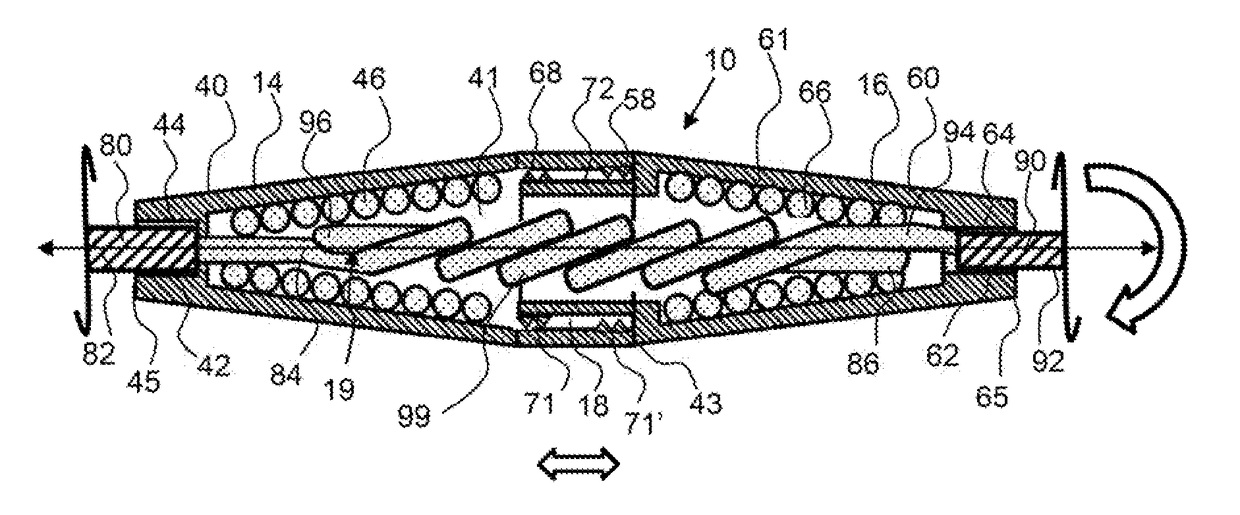
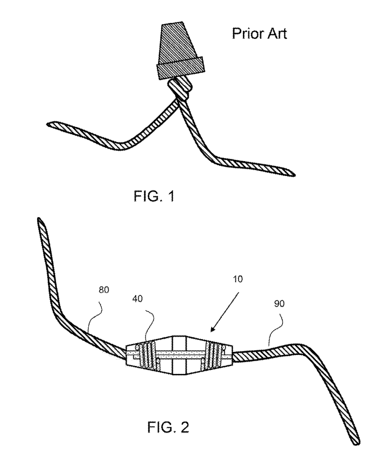
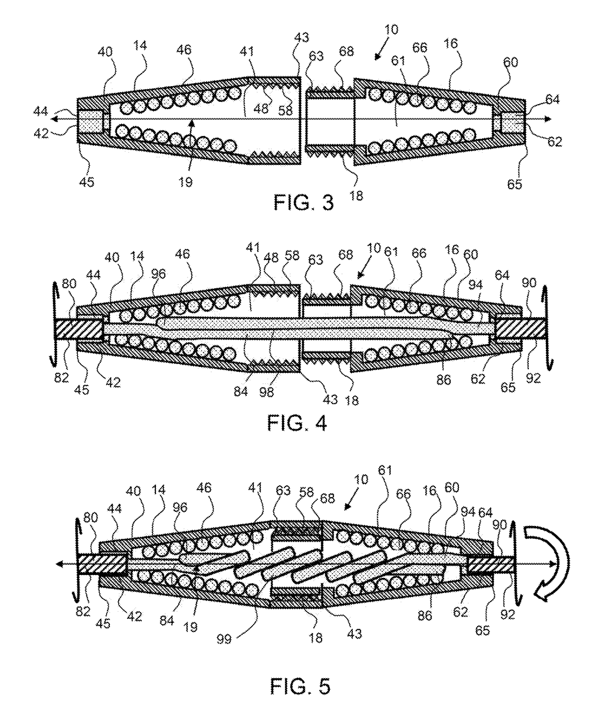
[0032]Corresponding reference characters indicate corresponding parts throughout the several views of the figures. The figures represent an illustration of some of the embodiments of the present invention and are not to be construed as limiting the scope of the invention in any manner. Further, the figures are not necessarily to scale, some features may be exaggerated to show details of particular components. Therefore, specific structural and functional details disclosed herein are not to be interpreted as limiting, but merely as a representative basis for teaching one skilled in the art to variously employ the present invention.

[0033]As used herein, the terms “comprises,”“comprising,”“includes,”“including,”“has,”“having” or any other variation thereof, are intended to cover a non-exclusive inclusion. For example, a process, method, article, or apparatus that comprises a list of elements is not necessarily limited to only those elements but may include other elements not expressly ...


PUM


Abstract

An in-line wire connector has a connector body with two insert ends on opposing ends for receiving a first and a second wire into apertures. A truncated tapered coil is configured within the connector body to secure the first and second wires to the in-line wire connector. The in-line twist on wire connector connects wires in line and may be low profile to allow the wires and the wire connector to slide through apertures and tight spaces as it often required in construction and remodeling projects. An in-line wire connector may have two truncated tapered coils that taper toward the opposing ends. A first and second wire conductor extend past each other toward opposing insert ends to produce an overlap portion to create electrical contact between wires. When the connector body is rotated, the wires rotate about each other and are retained by the tapered coil.

Description

CROSS REFERENCE TO RELATED APPLICATIONS[0001]The application is a divisional application of U.S. patent application Ser. No. 15 / 397,794, filed on Jan. 4, 2017, and currently pending.BACKGROUND OF THE INVENTIONField of the Invention[0002]The invention relates to wire connectors, and in particular, in-line twist connectors having a truncated tapered coil.Background[0003]Connecting the ends of electrical wires is typically accomplished by a conventional wire nut twist on connector. As shown in FIG. 1, a wire nut connector has an open end for the insertion of the conductors of two or more wires and a truncating wire coil. When the wire nut is twisted with respect to the two or more wires, the truncated tapered coil wire coil bites into the wires as the wires are twisted about each other and retained. This is an effective connector for many situations, however when wires need to be connected and subsequently pulled through conduits, this connection is not suitable as the wire nut protrud...

Claims


Application Information

Patent Timeline
Patent Type & Authority Applications(United States)
IPC IPC(8): H01R4/12
CPCH01R4/12
Inventor ZUKOWSKI, STANISLAW L.
Owner ZUKOWSKI STANISLAW L
Why Eureka
Try Eureka