Systems and methods for additive manufacturing recoating

a technology of additive manufacturing and recoating method, which is applied in the direction of additive manufacturing process, manufacturing tools, welding/soldering/cutting articles, etc., can solve the problems of melting pool, inability to evenly distribute the particulate material to form the next build layer, and inability to inhibit the rapid production of additive manufacturing process

Active Publication Date: 2018-07-12
GENERAL ELECTRIC CO
View PDF2 Cites 17 Cited by
  • Summary
  • Abstract
  • Description
  • Claims
  • Application Information

AI Technical Summary

Problems solved by technology

The focused energy source device melts the particulate material on the build platform in and around the area where the focused energy source is incident on the particulate material, resulting in a melt pool.
Evenly distributing the particulate material to form the next build layer is difficult because of many factors, and inhibits rapid production in the additive manufacturing process.
Voids in the part resulting from uneven distribution of the particulate material can result in the part being rejected or

Method used


Image

  • Systems and methods for additive manufacturing recoating
  • Systems and methods for additive manufacturing recoating
  • Systems and methods for additive manufacturing recoating

Examples


Embodiment Construction

[0017]In the following specification and the claims, reference will be made to a number of terms, which shall be defined to have the following meanings.

[0018]The singular forms “a”, “an”, and “the” include plural references unless the context clearly dictates otherwise.

[0019]“Optional” or “optionally” means that the subsequently described event or circumstance may or may not occur, and that the description includes instances where the event occurs and instances where it does not.

[0020]Approximating language, as used herein throughout the specification and claims, may be applied to modify any quantitative representation that could permissibly vary without resulting in a change in the basic function to which it is related. Accordingly, a value modified by a term or terms, such as “about”, “approximately”, and “substantially”, are not to be limited to the precise value specified. In at least some instances, the approximating language may correspond to the precision of an instrument for...


PUM

PropertyMeasurementUnit
Flexibilityaaaaaaaaaa
Shapeaaaaaaaaaa
Dimensionaaaaaaaaaa

Abstract

A recoating device for an additive manufacturing system includes a plurality of recoater blades which include a first stage and a second stage. The first stage includes a plurality of rows of the plurality of recoater blades and extends in the transverse dimension. The second stage includes a plurality of recoater blades and is configured substantially similar to the first stage of the plurality of recoater blades. The second stage of recoater blades is displaced from the first stage of recoater blades in the vertical dimension.

Description

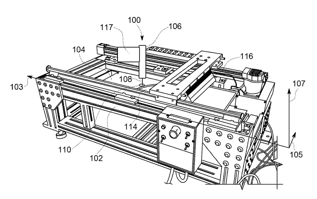
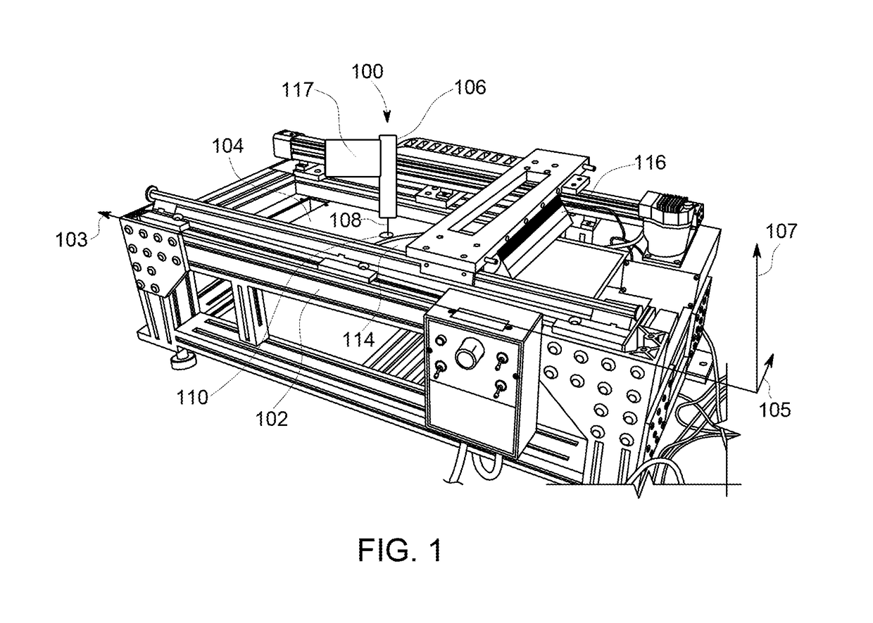
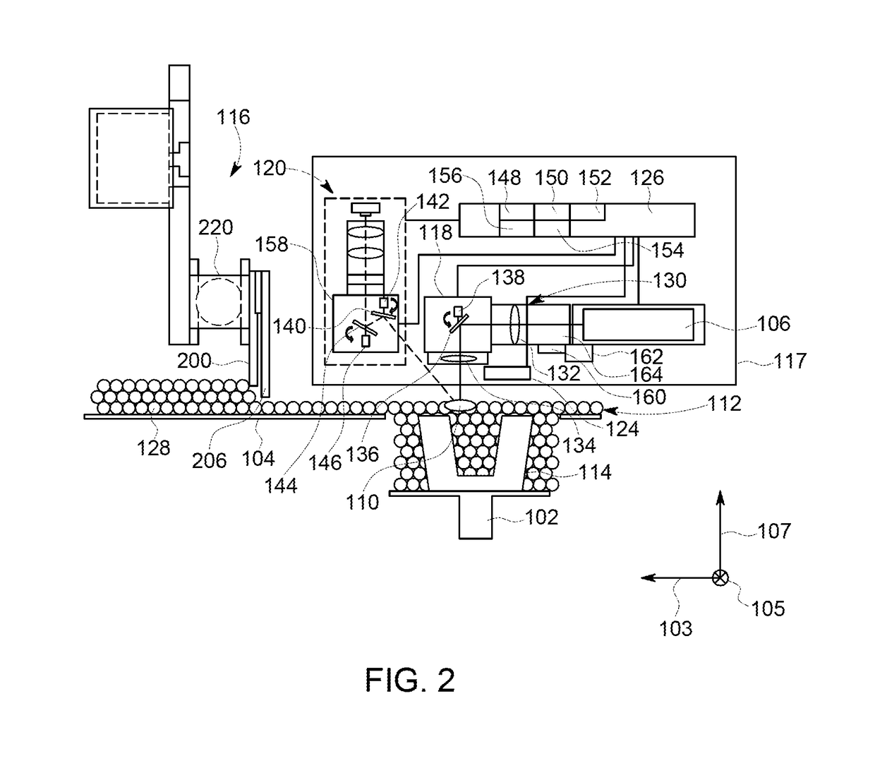
BACKGROUND[0001]The field of the disclosure relates generally to additive manufacturing systems and, more particularly, to systems and methods for recoating a component during the additive manufacturing process.[0002]At least some additive manufacturing systems involve the buildup of a particulate material to make a component. This method can produce complex components from expensive materials at a reduced cost and with improved manufacturing efficiency. At least some known additive manufacturing systems, such as Direct Metal Laser Melting (DMLM), Selective Laser Sintering (SLS), Direct Metal Laser Sintering (DMLS) and LaserCusing systems, fabricate components using a focused energy source, such as a laser device or an electron beam generator, a build platform, and a particulate, such as, without limitation, a powdered metal. The focused energy source device melts the particulate material on the build platform in and around the area where the focused energy source is incident on the...

Claims


Application Information

Patent Timeline
IPC IPC(8): B29C67/00B33Y10/00B33Y30/00B33Y80/00B28B1/00B23K26/342
CPCB29C67/0085B29C67/0077B33Y10/00B33Y30/00B23K2203/14B28B1/001B23K26/342B29K2105/251B23K2203/10B33Y80/00B29C64/153B22F3/004B22F2999/00B29C64/214Y02P10/25B22F12/67B22F10/36B22F10/28B22F10/32B23K2103/10B23K2103/14B29C64/20
Inventor SHI, JINJIEBOGDAN, JR., DAVID CHARLESCARTER, WILLIAM THOMASHAYDEN, CHRISTOPHER JAMES
Owner GENERAL ELECTRIC CO
Why Eureka
Try Eureka