Well Stimulation and Cleaning Tool

a technology for cleaning tools and wells, applied in the direction of fluid removal, drilling accessories, borehole/well accessories, etc., can solve the problem that the switch will stop working, and achieve the effect of smooth inside the tool body, reducing the stoppage of pulsating fluid flow, and exceeding the magnitude of for

Active Publication Date: 2018-07-12
REX A DODD LLC
View PDF1 Cites 4 Cited by
  • Summary
  • Abstract
  • Description
  • Claims
  • Application Information

AI Technical Summary

Benefits of technology

[0011]A further advantage of the present invention is that the diffuser legs and the crossover channel can have non-circular cross-sections, meaning that the tool internal can be made by cutting a substantially cylindrical steel shaft in half along its longitudinal axis and then machining the fluid flow paths through the diffuser legs as grooves or channels in the facing surfaces. This avoids having to drill the diffuser legs and intersecting lateral crossover channel into a single metal shaft, and then plug off the end of the bore drilled for the crossover channel. If desired, a cooperating tongue and groove can also be machined into oppositely disposed, facing surfaces of the tool internals to limit relative movement of the two halves during assembly of the subject tool. A substantially cylindrical retainer ring can be machined from a hollow steel shaft of suitable dimensions that is cooperatively sized and configured to slidably engage the inside wall of the tool body and also serve as the inside wall of the lower chamber.
[0012]During assembly of the tool, the two halves of the tool internal and the retainer ring can desirably be placed into facing and contacting engagement with each other and then lubricated with white oil on the outwardly facing surfaces to aid in sliding them smoothly inside the tool body. Optionally, one half of the tool internal can be fabricated with one or more lips or projections disposed at or near the perimeter and is engageable with a cooperatively sized and configured recess in the other half to resist relative sliding movement between the two halves as they are placed in facing and abutting contact with each other and inserted into the open lower end of the tool body. After the tool internal and retainer ring are inserted into the tool body, they can be held in place by standard threaded connections disposed between the tool body and other elements of the string.
[0013]The subject well stimulation and cleaning tool comprises a fluidic switch that is specially configured by the provision of a second, longitudinally spaced-apart chamber inside the tool to alleviate stoppage of pulsating fluid flow due to plugging of an outlet port downstream of the splitter. More particularly, one embodiment of the subject tool is desirably configured to recombine divergent flow paths through the diffuser legs into a single pulsed fluid flow channel disposed below the splitter that is discharged into the secondary chamber before the pulsed fluid flow reaches the tool exit port or ports. The recombined, pulsed fluid flow then exits the tool from the secondary chamber through one or a plurality of discharge ports and creates a cyclic shock wave in the backside fluid (fluid disposed between the tubing and the well bore) that is propagated in all directions and significantly exceeds the magnitude of the force experienced using a well stimulation or cleaning tool having a non-pulsating jet flow or having a conventional oscillation chamber disposed above the splitter and the same number and configuration of discharge ports operating at the same fluid throughput. Furthermore, the improved tool configuration of the present invention is particularly effective for unplugging ports that have become blocked without tripping the tool.
[0014]In the subject tool, recombination desirably occurs downstream of any crossover channel or vacuum port disposed in the splitter. The divergent fluid flow paths through a splitter can be recombined by causing them to converge and intersect to form a common fluid flow path or by causing each of them to flow into a third fluid path that interconnects the downstream ends of the two diffuser legs and provides a common fluid collecting passage that establishes fluid communication between the lower end of each of the legs and the fluid discharge port or ports of the tool. This recombination of fluid flow paths enables the tool to continue producing a pulsed flow upstream of any plugging or blockage in one or more fluid discharge ports, and further intensifies that pulsed flow in the secondary chamber to assist in removing the plugging or blockage so as not to totally or partially disable the tool downhole or require tripping the tool to unplug the discharge ports.
[0015]According to another embodiment of the invention, a well stimulation and cleaning tool is disclosed that comprises a fluid switch with a splitter having diffuser legs that are not redirected into a single flow path at the bottom of the splitter but are instead configured to discharge pulsed fluid exiting each of the splitter legs directly into a secondary chamber disposed downstream of the splitter to intensify the magnitude of the fluid pulses before the fluid exits the tool through one or more fluid discharge ports and to protect the diffuser legs of the well stimulation and cleaning tool and the fluid discharge ports of any nose block or other tool attached to the downstream side of the well stimulation and cleaning tool from plugging.
[0016]According to yet another embodiment of the invention, a bit sub is disclosed that is structurally analogous to one or more of the embodiments disclosed above except that the porting is desirably larger to prevent washing of the ports and plugging of the bit ports.

Problems solved by technology

However, if one of the legs becomes plugged, the switch will stop working.

Method used


Image

  • Well Stimulation and Cleaning Tool
  • Well Stimulation and Cleaning Tool
  • Well Stimulation and Cleaning Tool

Examples


Embodiment Construction

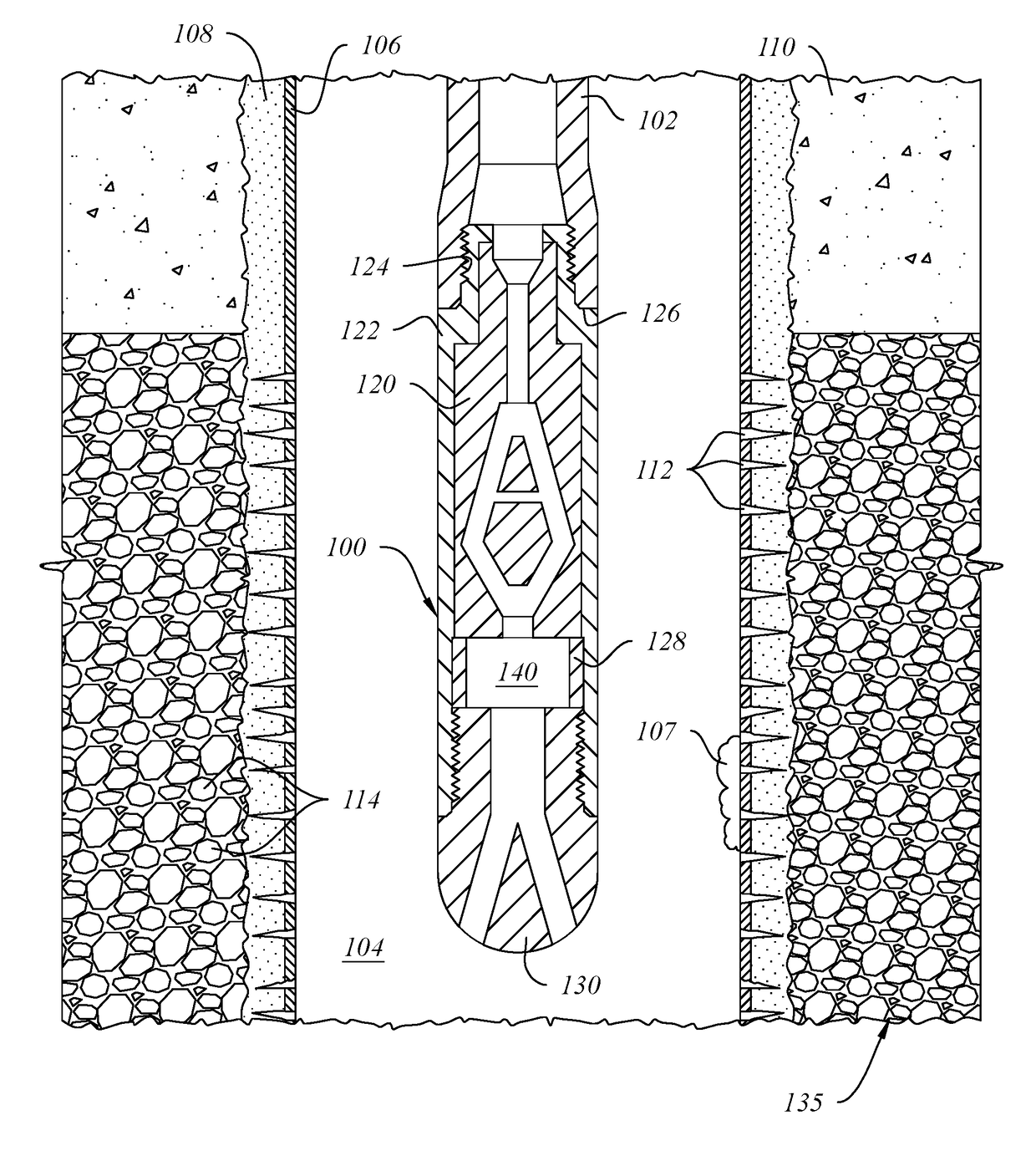
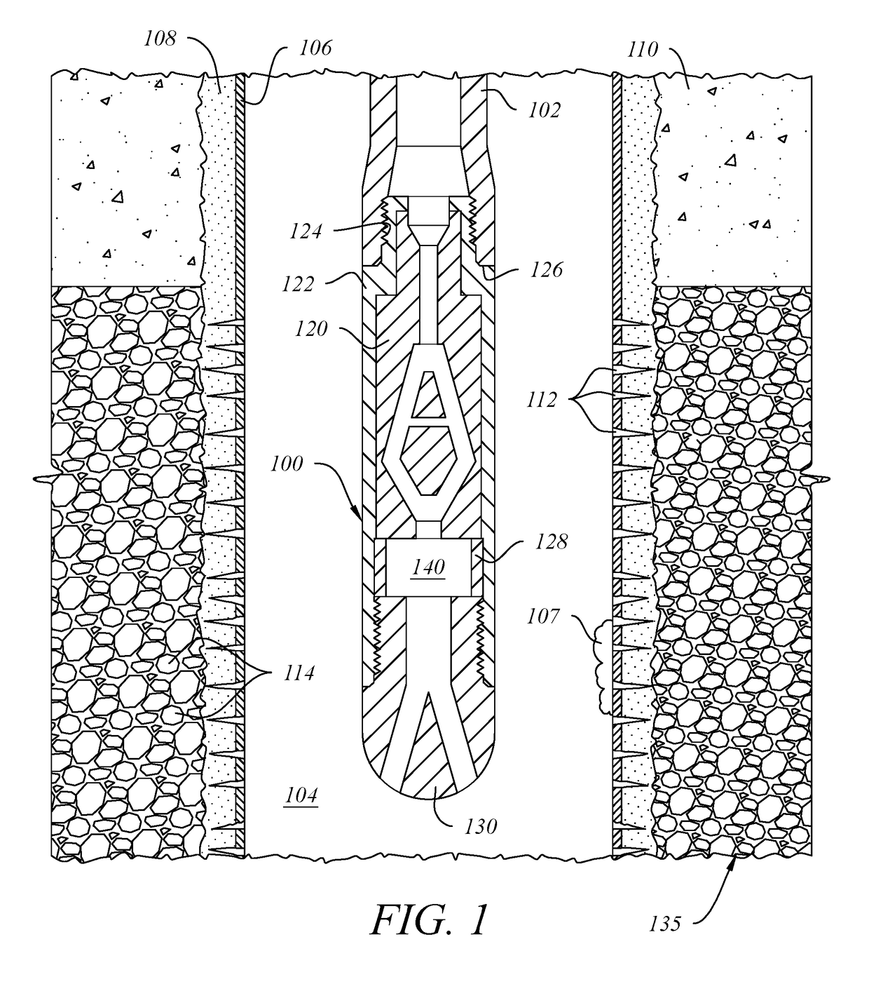
[0030]Referring to FIG. 1, tool 100 is depicted as being suspended from tubing 102 inside bore 104 of a subterranean well in which casing 106 is held in place by cement 108. Casing 106 further comprises a plurality of perforations 112 through which the surrounding formation 110 (as depicted above perforations 112) has been fractured into smaller particles 114 to increase its permeability. At one location inside casing 106, mineral scale 107 has formed on the inside of the casing and has blocked some of perforations 112, thereby reducing the ability to inject fluids or proppants into or recover fluids from formation 135. Tool 100 further comprises tool body 122 having an externally threaded pin end 124 that engages the internally threaded box end of tubing 102, with downwardly facing shoulder 126 of tubing 102 shown in abutting contact with an upwardly facing annular collar of tool body 122. Tool internal 120 (one of two opposed halves) is disposed in sliding engagement with tool bod...


PUM


Abstract

A subterranean well stimulation and cleaning tool comprising an upper chamber, a splitter, at least two diffuser legs having proximal ends in fluid communication with the upper chamber and distal ends in fluid communication with a lower chamber, and a laterally disposed crossover channel connecting the at least two diffuser legs between the proximal and distal ends, whereby fluid pulses are generated inside the upper chamber from a substantially constant fluid flow received into the tool from the well surface and are alternately directed through the at least two diffuser legs and into the lower chamber, where the fluid pulses are intensified prior to discharging them from the tool through a nose block or other device disposed downstream of the tool.

Description

1. FIELD OF THE INVENTION[0001]This invention relates to a well stimulation and cleaning tool having no moving parts that desirably improves production from subterranean wells, including without limitation production from oil and gas wells, by creating subsurface pulses in a fluid medium that is pumped downhole at a substantially constant flow rate. The fluid medium can be selected from aqueous and non-aqueous liquids, gasses, and foamed liquids, and can further comprises various additives commonly used in such fluids. The subject tool desirably comprises a fluidic switch or oscillator that generates a pulsed fluid flow downhole in combination with a secondary chamber that intensifies the pulsed fluid flow prior to discharging the fluid medium into a well bore. Where a standing fluid is present inside the well bore, the fluidic pulses emanating from the tool are propagated through the standing fluid prior to contacting the surrounding structures or formation. The subject tool can be...

Claims


Application Information

Patent Timeline
Patent Type & Authority Applications(United States)
IPC IPC(8): E21B37/00E21B43/25
CPCE21B37/00E21B7/18E21B10/60E21B43/25E21B41/0078E21B37/08
Inventor DODD, REX A.
Owner REX A DODD LLC
Why Eureka
Try Eureka