Magnet

a rare earth magnet and magnet technology, applied in the field of magnets, can solve the problems of wasting expensive dysprosium or terbium, affecting requiring a considerable amount of time to deposit the material, so as to reduce the overall magnetic field strength of the magnet, improve the performance of the magnet, and increase coercivity

Pending Publication Date: 2018-07-12
DYSON TECH LTD
View PDF0 Cites 3 Cited by
  • Summary
  • Abstract
  • Description
  • Claims
  • Application Information

AI Technical Summary

Benefits of technology

[0019]The coercivity of conventional neodymium magnets however can suffer at elevated temperatures. It has been found that substituting an amount (typically as much as 12%) of neodymium for dysprosium in the crystal lattice can significantly increase coercivity and improve the performance of the magnet at elevated temperatures.
[0020]When depositing dysprosium onto a neodymium magnetic surface, the diffused dysprosium magnetically couples anti-parallel to the neodymium which in turn reduces the overall magnetic field strength of the magnet. However, by controlling and limiting the amount of dysprosium that is deposited onto the surface, the overall impact on the remanence of the magnet will be less than a full uniform coating of dysprosium. The neodymium alloy may be Nd2Fe14B which exhibits a particularly improved magnet. It is believed that the improvement in coercivity is due to Dy2Fe14B and (Dy,Nd)2Fe14B having a higher anisotropy field than Nd2Fe14B.
[0021]The Nd2Fe14B alloy magnet may comprise grains of Nd2Fe14B with a shell layer comprising Dy2Fe14B or (Dy,Nd)2Fe14B, the shell layer having a thickness of about 0.5 μm. The deposited dysprosium diffuses through the magnetic body during a heat-treatment after depositing the cold sprayed bead of dysprosium on the magnetic body. During the heat-treatment, the deposited dysprosium substitutes with neodymium atoms along the grain boundaries of the crystal lattice, instead of permeating throughout the bulk of the crystal lattice. The shell layer of the grains produced by cold spray and heat-treatment can be controlled and hence much thinner compared to magnets produced by other methods. The shell layer can have a thickness of 0.5 μm. Therefore a much higher concentration of dysprosium is present at the grain boundaries, meaning that less dysprosium is needed to achieve the same coercivity enhancement that is exhibited in conventional dysprosium substituted rare earth magnets.
[0022]The deposition thickness of the bead of dysprosium may be between 1 to 5 μm. This thickness results in effective grain boundary diffusion during heat treatment and also reduces wastage of expensive dysprosium. The bead of dysprosium should have an average deposition thickness of 1 to 5 μm since a bead with a uniform deposition thickness is not required.

Problems solved by technology

A problem with these deposition techniques is that a considerable amount of time may be required to deposit the dysprosium or terbium, and that wastage of expensive dysprosium or terbium can still occur.
It is also considered that some dysprosium containing materials used in current deposition techniques, for example DyF3, may be detrimental to the magnetic properties of the substrate.

Method used


Image

  • Magnet
  • Magnet
  • Magnet

Examples


Embodiment Construction

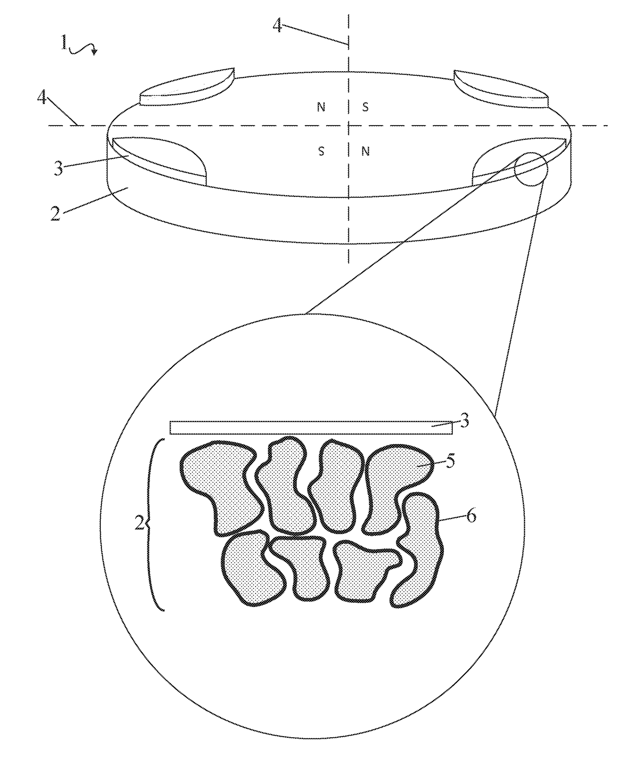
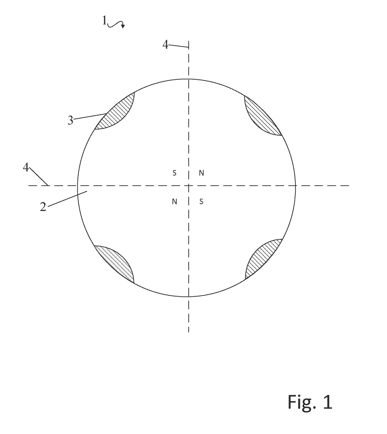
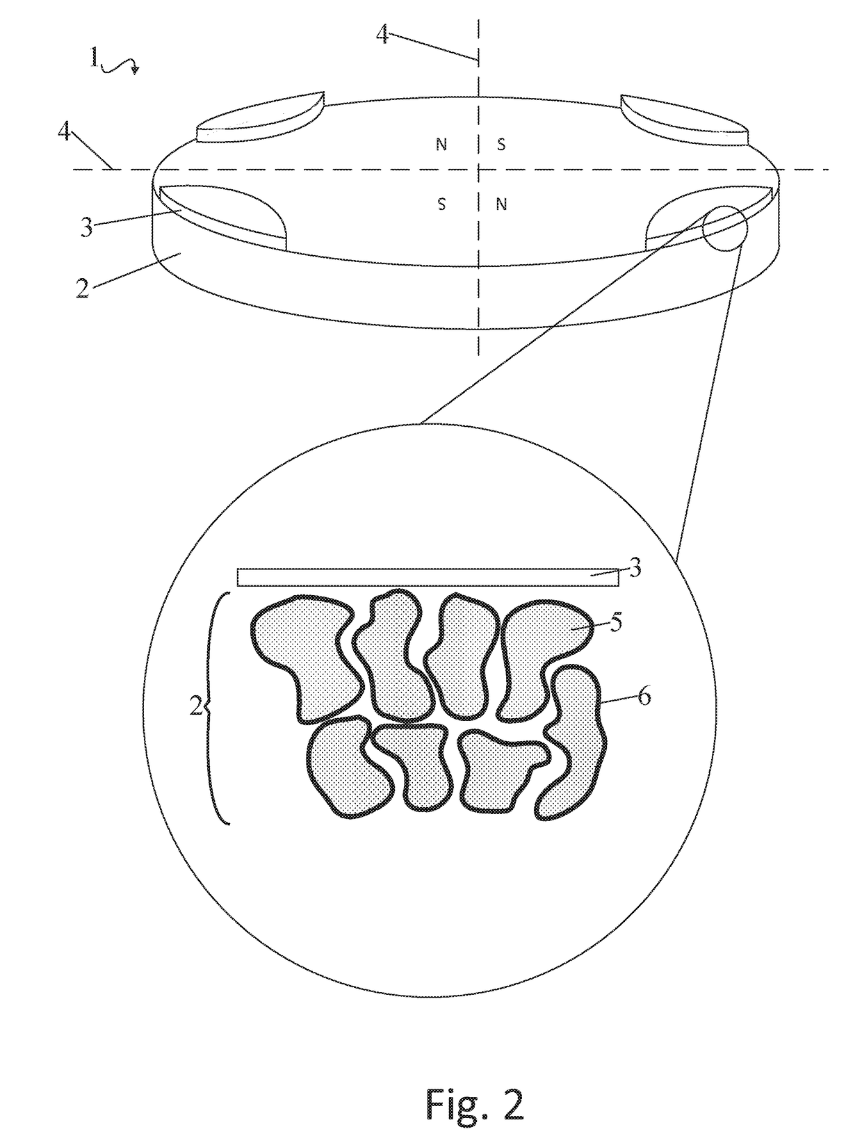
[0031]The magnet 1 of FIGS. 1, 2, and 3 comprises a cylindrically shaped magnetic body 2 and beads of dysprosium metal 3 deposited on a surface of the magnetic body 2. The magnet 1 is shown as having four poles, which are shown as being geometrically divided by pole intersections 4. Each pole of the magnet 1 has a region of high magnetic field density which is positioned in-between the pole intersection 4.

[0032]The magnetic body 2 comprises sintered grains 6 of a rare earth alloy. The grains 5 are shown as discrete granules with a boundary. Specifically, the bulk substance within the grains 5 comprises a Nd2Fe14B alloy. The grains 5 adjacent the deposited bead each have a shell layer 7 around their boundary. The shell layer 6 comprises diffused dysprosium which has substituted into the crystal lattice structure of the rare earth alloy. Although dysprosium can diffuse into the bulk of the crystal structure within the grains 5, careful control of the heat treatment conditions allow fo...


PUM

PropertyMeasurementUnit
temperatureaaaaaaaaaa
thicknessaaaaaaaaaa

Abstract

Magnets and systems, methods, and techniques for manufacturing magnets are provided. In some embodiments, methods of manufacturing magnets comprise providing a rare earth magnetic body depositing a bead of dysprosium or terbium metal onto a part of the magnetic body to form a magnet; and heat-treating the magnet. In some embodiments, a magnet is provided comprising a magnetic body and a bead of dysprosium or terbium metal. In some embodiments, the magnetic body contains grains of rare earth magnet alloy, and the bead of dysprosium or terbium metal is deposited onto a part only of a surface of the magnetic body.

Description

REFERENCE TO RELATED APPLICATIONS[0001]This application is a national stage application under 35 USC 371 of International Application No. PCT / GB2016 / 051945, filed Jun. 29, 2016, which claims the priority of United Kingdom Application No. 1511822.7, filed Jul. 6, 2015, the entire contents of which are incorporated herein by reference.FIELD OF THE INVENTION[0002]The present invention relates to rare earth magnets and methods of making rare earth magnets. More specifically, the present invention relates to rare earth magnets with improved coercivity and methods of making the same.BACKGROUND OF THE INVENTION[0003]Rare earth magnets may comprise a crystal lattice structure containing grains of rare earth alloys. It has been shown that the magnetic properties, particularly the coercivity, of such magnets can be improved by substituting rare earth magnetic elements such as dysprosium or terbium into the crystal lattice structure. Dysprosium or terbium can be substituted either into the bul...

Claims


Application Information

Patent Timeline
Patent Type & Authority Applications(United States)
IPC IPC(8): H01F1/057H01F41/02
CPCH01F1/0577H01F41/0293H01F1/053
Inventor CELIK, TUNCAY
Owner DYSON TECH LTD
Why Eureka
Try Eureka