Solar cell module and method of manufacture thereof

a solar cell and module technology, applied in the field of solar cell modules, can solve the problems of low sensitivity of solar cell modules in shorter wavelength regions, inability to make effective use of shorter wavelength light, and insufficient quantity of ultraviolet light by phosphor alone, and achieve high efficiency

Inactive Publication Date: 2018-07-12
PANASONIC INTELLECTUAL PROPERTY MANAGEMENT CO LTD
View PDF4 Cites 1 Cited by
  • Summary
  • Abstract
  • Description
  • Claims
  • Application Information

AI Technical Summary

Benefits of technology

[0008]The present disclosure is intended to find a solution to the foregoing problems, and it is an object of the present disclosure to provide a solar cell module with which high output can be achieved through wavelength conversion of shorter wavelength light to longer wavelength light while extending life by removing ultraviolet light. The disclosure is also intended to provide a method for manufacturing the solar cell module.
[0025]In the configuration of the solar cell module of the aspect of the present disclosure, the second encapsulant layer that is disposed closer to the light incident side than the photoelectric conversion device has a phosphor concentrated region formed by concentrating phosphors in the vicinity of the surface of the UV absorber layer on the side of the protective glass. In this way, the UV absorber does not easily migrate to the protective glass side around the phosphors, and is unlikely to interfere with the absorption of UV light by the phosphors. The UV light absorbing effect of the UV absorber protects the photoelectric conversion device from UV damage. In this way, the high efficiency achieved by wavelength conversion can be maintained for extended time periods in the solar cell module.

Problems solved by technology

Solar cell modules typically have low sensitivity in shorter wavelength regions, and fail to make effective use of shorter wavelength light, including the ultraviolet light in sunlight.
However, in many cases, the phosphor cannot absorb sufficient quantities of ultraviolet light by itself, and needs to be used along with a UV absorber.
This results in the phosphor emitting smaller quantities of light, and it becomes difficult to improve efficiency by wavelength conversion.
However, with the configuration of JP-A-2011-238639, the phosphor absorbs the light of longer wavelengths, which is effectively used by the photoelectric conversion device, and a proportional efficiency drop is unavoidable.
Accordingly, the phosphor layer is directly exposed to the outdoor environment, and the phosphor quickly deteriorates.
This causes a decrease in the quantity of emitted light from the phosphor, and it becomes difficult to achieve high efficiency.

Method used


Image

  • Solar cell module and method of manufacture thereof
  • Solar cell module and method of manufacture thereof
  • Solar cell module and method of manufacture thereof

Examples


first embodiment

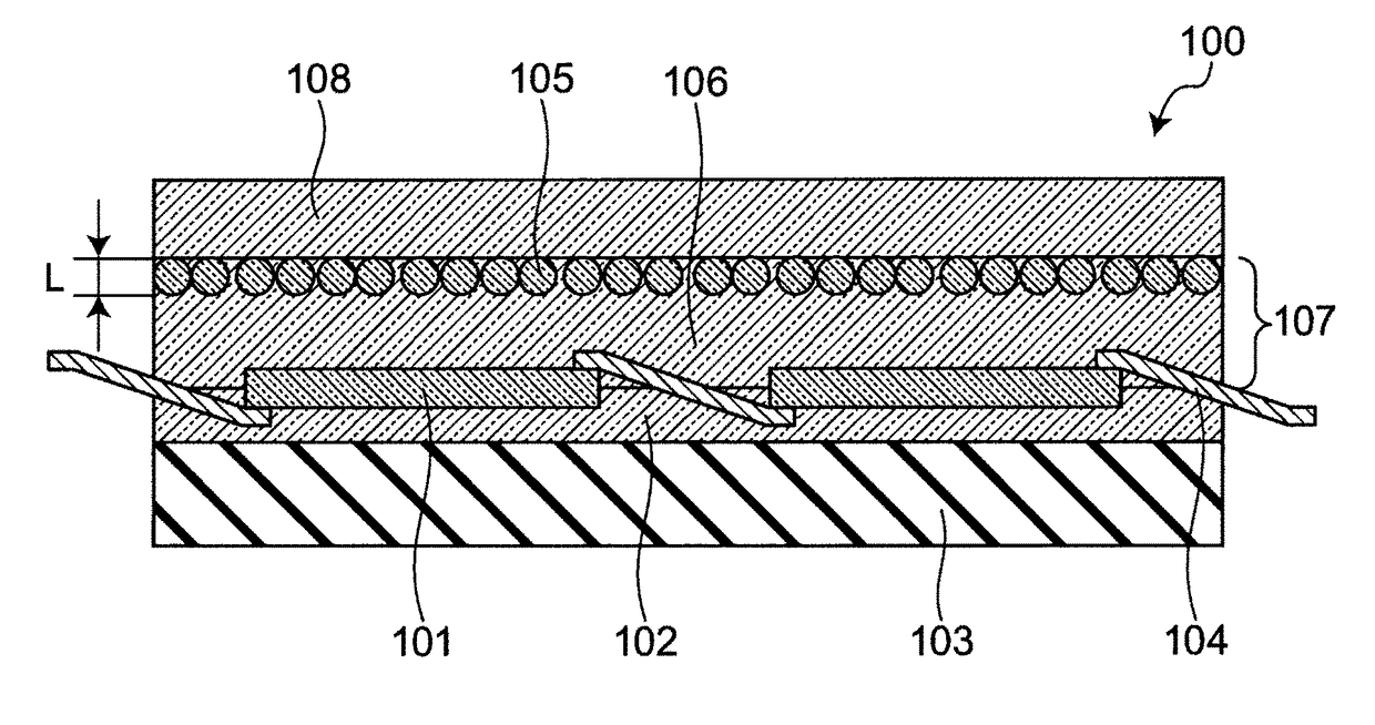
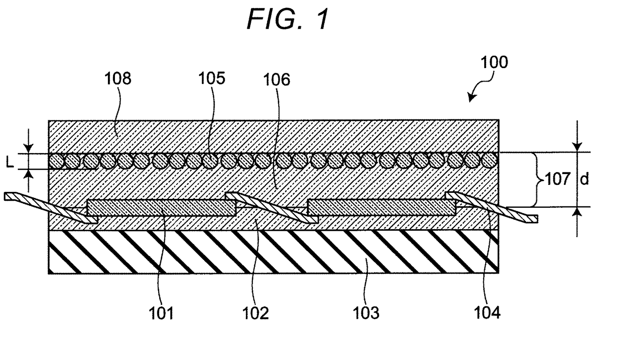
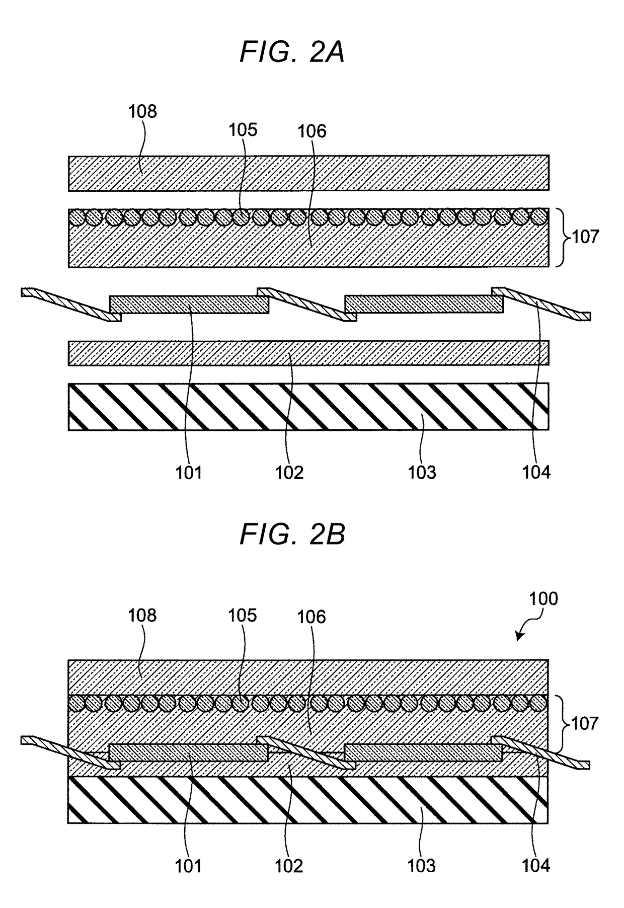
[0054]FIG. 1 is a cross sectional view illustrating a cross sectional structure of a solar cell module 100 according to First Embodiment. The solar cell module 100 according to the present First Embodiment includes at least a photoelectric conversion device 101, a first encapsulant layer 102, a back sheet 103, an electrode 104, a second encapsulant layer 107, and a protective glass 108. The solar cell module 100 is structured so that the back sheet 103, the first encapsulant layer 102, the photoelectric conversion device 101, the second encapsulant layer 107, and the protective glass 108 are stacked in this order. The first encapsulant layer 102 is formed of a transparent resin provided on the back of the photoelectric conversion device 101 for protection. The photoelectric conversion device is electrically connected to the electrode 104. The second encapsulant layer 107 is a sheet configured from a resin containing a UV absorber. Specifically, the solar cell module 100 has a struct...

example 1

[0092]Example 1 represents an example in which a solar cell module for evaluation was produced according manufacturing method A. As the phosphor, a silica phosphor that had been formed by sintering was used after fine phosphor particles having an Eu2+ emission center were embedded in porous portions of a porous silica filler. The silica phosphor had an average particle size of 1.0 μm. For the production of the UV absorber layer, 1 g of benzophenone UV absorber 2,4-dihydroxybenzophenone was added to 200 g of a low-density polyethylene resin, and mixed at 100 rpm for about 30 minutes in a planetary mixer that had been heated to 150° C. The mixture was then pressed with a heat press that had been heated to 150° C., after adjusting the gap with a 550-μm stainless steel spacer. This was followed by cooling to obtain the UV absorber layer. Thereafter, the silica phosphor was applied to one surface of the UV absorber layer in an amount of about 300 μg per 1 cm2, using a brush, and the UV a...

examples 2 to 8

[0093]Example 2 is the same as Example 1, except that the silica phosphor had an average particle size of 50 μm, and the phosphor concentrated region had a thickness of 50 μm.

[0094]Example 3 is the same as Example 1, except that the silica phosphor had an average particle size of 0.05 μm, and the phosphor concentrated region had a thickness of 0.05 μm.

[0095]Example 4 is the same as Example 1, except that the silica phosphor had an average particle size of 50 μm, the phosphor was repeatedly applied and embedded in the UV absorber layer 5 times, the phosphor concentrated region had a thickness of 250 μm, and the UV absorber layer had a thickness of 1,000 μm.

[0096]Example 5 is the same as Example 1, except that manufacturing method B was used. The method did not allow for measurement of transmittance at 370 nm. However, the measured value of Example 1 was used because the configuration was the same.

[0097]Example 6 is the same as Example 1, except that the phosphor is an inorganic phosp...


PUM


Abstract

A solar cell module having an extended lifetime and improved efficiency achieved by improved solar cell efficiency, and reduced UV damage to the photoelectric conversion device. The solar cell module has a structure in which a back sheet, a first encapsulant layer, a photoelectric conversion device electrically connected to an electrode, a second encapsulant layer, and a protective glass are stacked in that order. The second encapsulant layer is a sheet configured from a resin containing a UV absorber, and the sheet contains phosphors that are concentrated on the side of the protective glass, as opposed to the side of the first encapsulant layer.

Description

TECHNICAL FIELD[0001]The technical field relates to a solar cell module, and a method of manufacture thereof.BACKGROUND[0002]Solar cell modules typically have low sensitivity in shorter wavelength regions, and fail to make effective use of shorter wavelength light, including the ultraviolet light in sunlight. Phosphor is a substance that absorbs light of shorter wavelength regions and fluoresces light of longer wavelength regions. It has been used as a wavelength conversion material to increase the quantity of longer wavelength light and to improve the output of a solar cell module.[0003]The photoelectric conversion device of a solar cell module deteriorates after prolonged exposure to ultraviolet (UV) light. Thus it is desirable to take measures to remove the UV component from the light that falls on the photoelectric conversion device. For this purpose, a UV absorber is typically used in the front filler of the photoelectric conversion device. Such a UV absorber would not be neces...

Claims


Application Information

Patent Timeline
Patent Type & Authority Applications(United States)
IPC IPC(8): H01L31/055H01L31/049H01L31/048H01L31/05
CPCH01L31/055H01L31/049H01L31/0481H01L31/0504Y02E10/52
Inventor TOYOTA, KEIMORI, MASATOAKIYAMA, SHINNOSUKE
Owner PANASONIC INTELLECTUAL PROPERTY MANAGEMENT CO LTD
Why Eureka
Try Eureka