
Recording apparatus

Active Publication Date: 2018-07-19
SEIKO EPSON CORP
View PDF2 Cites 3 Cited by
  • Summary
  • Abstract
  • Description
  • Claims
  • Application Information

AI Technical Summary

Benefits of technology

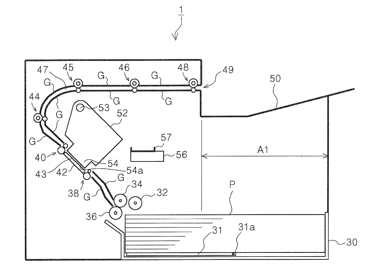
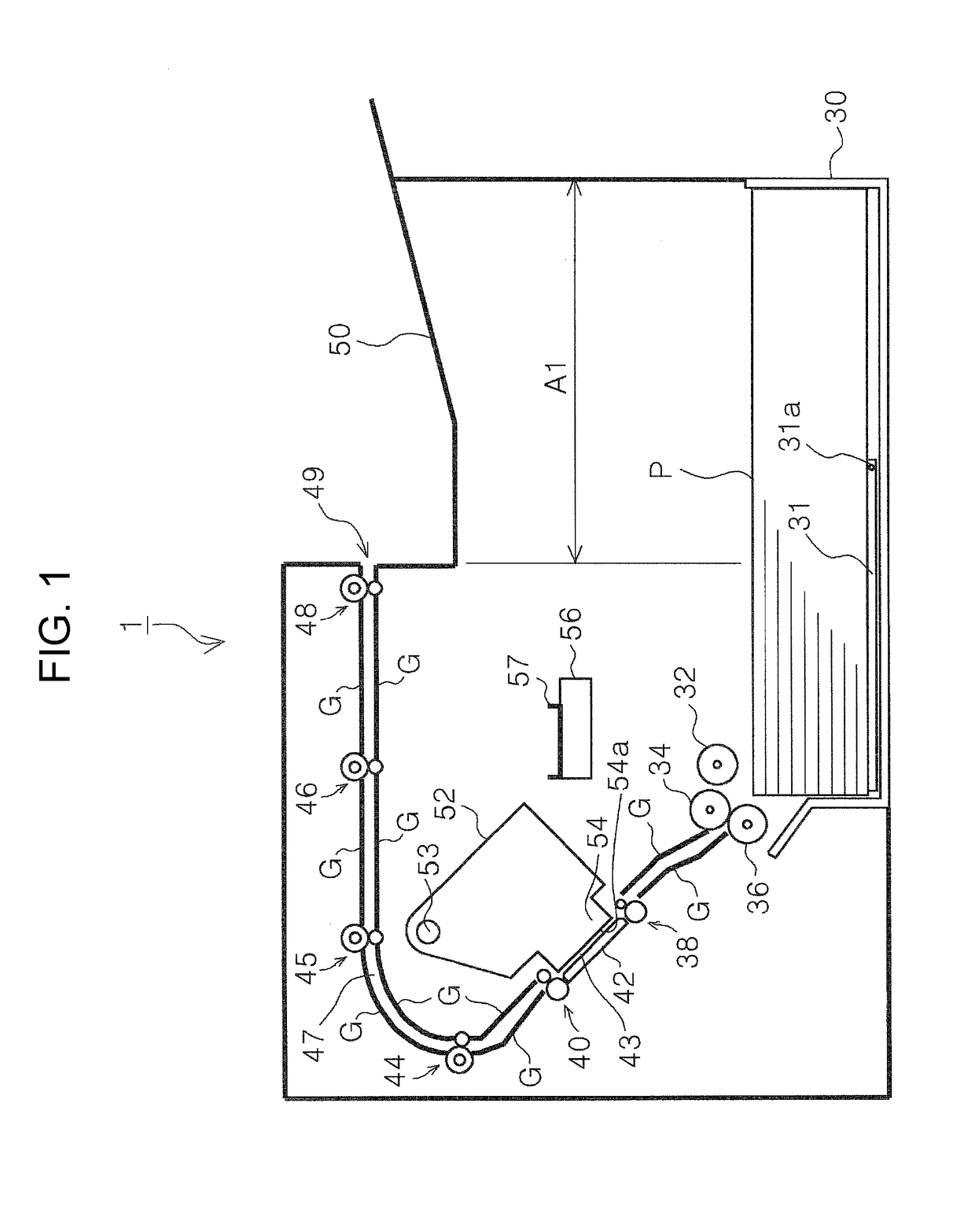
This patent is about a recording apparatus that can perform maintenance on a recording head while reducing the size of the apparatus. The apparatus includes a recording head, a transportation path, and a maintenance unit. By inclining the head facing region and making the recording head rotatable, the apparatus can switch between a position for performing recording and a position for performing maintenance. This reduces the space needed for the components and prevents an increase in the size of the apparatus or a paper jam in the transportation path. The maintenance unit is positioned close enough to the recording head to perform maintenance when it is switched from the recording position to the maintenance position, which further reduces the size of the apparatus. The coordination mechanism displaces the maintenance unit in coordination with the positional switching of the recording head, which eliminates the need for separate drive power sources, reducing the cost of the apparatus. The output path allows for face down output of the medium, which reduces the size of the apparatus in the height direction. Overall, this patent allows for efficient maintenance and downsizing of the recording apparatus.

Problems solved by technology

As a result, in the configuration described in JP-A-2013-78861, the up and down movement range of the maintenance unit needs to be increased to ensure the opening space of the platen, which requires a large dead space (a space in which other components cannot be provided), leading to an increase in size of the apparatus.
As a result, the up and down movement range of the recording head needs to be increased, which requires a large dead space (a space in which other components cannot be provided), leading to an increase in size of the apparatus as well.
Further, the configuration described in JP-A-2013-78861 has another technical problem.
Since the printer is configured to turn over the paper sheet picked up from the paper sheet cassette and transport the paper sheet to the position which faces the recording head, perform recording, and again turn over the recorded paper sheet to output the paper sheet onto the output tray, the size of the apparatus disadvantageously increases due to a long transportation path.
In addition, a paper jam in the transportation path is also likely to occur due to the long transportation path.

Method used


Image

  • Recording apparatus
  • Recording apparatus
  • Recording apparatus

Examples


second embodiment

[0063]In the above embodiment, the maintenance unit 56 moves to the horizontal direction and is then displaced between the maintenance position and the non-maintenance position. However, the movement is not limited thereto, and for example, the maintenance unit 56 may be configured to be horizontally displaced from the non-maintenance position to a position before the maintenance position as indicated by the arrow m in FIG. 5, and then displaced upward from the position before the maintenance position to the maintenance position as indicated by the arrow n. FIG. 5 illustrates the present disclosure, and the reference character 56B in FIG. 5 indicates the maintenance unit that performs the above displacement.

[0064]In this case, for example, the horizontal movement of the maintenance unit 56B (in the arrow m direction) may be performed by meshing the rack 84 with the pinion gear 86, and the upward movement (in the arrow n direction) may be performed by pushing up the maintenance unit ...

third embodiment

[0065]Further, although the maintenance unit 56 in the above embodiment moves in the horizontal direction, it may be configured to move in the vertical direction to thereby switch the non-maintenance position and the maintenance position. FIG. 6 illustrates the present disclosure, and the reference character 56C in FIG. 6 indicates the maintenance unit that displaces in the vertical direction (arrow s direction).

[0066]Further, although the head unit 52 in the above embodiment is configured to rotate by rotation of the unit driving gear 66 while the gear 52c meshes with the unit driving gear 66, various configuration can be used to rotate the head unit 52. FIG. 7 illustrates a fourth embodiment of the present disclosure, and the reference character 52B indicates the head unit according to the fourth embodiment. In the present embodiment, a wire 76 is attached to the head unit 52B. The wire 76 is configured to be taken up or to be unwound by a take-up pulley 74 via a driven pulley 72....

first embodiment

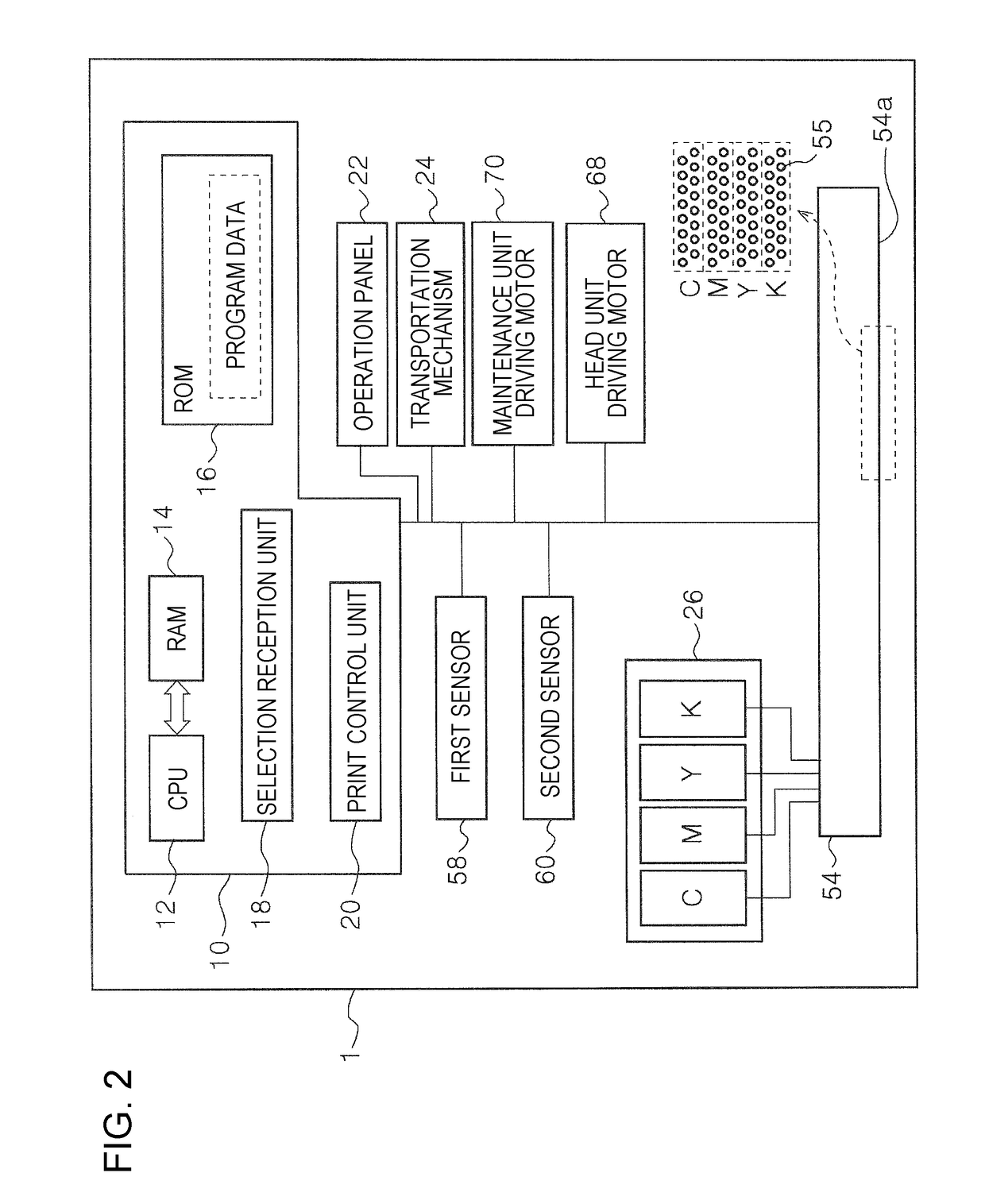
(1) In the first embodiment shown in FIGS. 3 and 4, the first sensor 58 and the second sensor 60 may be omitted. In this case, for example, an increase in drive current of the head unit driving motor 68 when the head unit 52 abuts the first abutment unit 62 or the second abutment unit 64 can be detected to thereby detect whether the head unit 52C is assuming the first position (inclined position) or the second position (horizontal position). Alternatively, the first abutment unit 62 and the second abutment unit 64 may be omitted. It is because that the head unit 52 can be positioned at the second position by stopping the head unit driving motor 68 when the first detected section 52a is detected by the first sensor 58, and the head unit 52 can be positioned at the first position by stopping the head unit driving motor 68 when the second detected section 52b is detected by the second sensor 60.

[0073](2) In the first embodiment shown in FIGS. 3 and 4, or in the other embodiments as wel...


PUM


Abstract

A recording apparatus includes: a recording head; a transportation path along which the medium is transported via a head facing region which faces the recording head; and a maintenance unit used for maintenance of the recording head, wherein the head facing region, which is a region of the transportation path which faces the recording head, is inclined with respect to a horizontal direction, and the recording head is provided to be rotatable, and when rotating, the recording head can be switched between a first position in which the head surface is inclined along an inclination of the head facing region, the first position being a position for performing recording, and a second position in which the head surface becomes horizontal or becomes more horizontal than in the first position, the second position being a position for performing maintenance by the maintenance unit.

Description

CROSS REFERENCES TO RELATED APPLICATIONS[0001]The entire disclosure of Japanese Patent Application Nos. 2017-006967, filed Jan. 18, 2017 and 2017-175977, filed Sep. 13, 2017 are expressly incorporated by reference herein.BACKGROUND1. Technical Field[0002]The present disclosure relates to recording apparatuses that perform recording onto a medium.2. Related Art[0003]Ink jet printers, which are examples of the recording apparatus, are configured to pick up a paper sheet from a paper sheet cassette, transport the paper sheet to a position which faces a recording head, perform recording onto the paper sheet, and output the recorded paper sheet. More specifically, one example of the printer is configured to turn over the paper sheet picked up from the paper sheet cassette, perform recording after the paper sheet is transported to the position which faces the recording head, and again turn over the recorded paper sheet to output the paper sheet face down onto an output tray. Typically, a ...

Claims


Application Information

Patent Timeline
IPC IPC(8): B41J2/165
CPCB41J2/16588B41J2/16547B41J2/145B41J2/16508B41J25/316
Inventor MORI, KAZUNORI
Owner SEIKO EPSON CORP
Features
  • Generate Ideas
  • Intellectual Property
  • Life Sciences
  • Materials
  • Tech Scout
  • Unparalleled Data Quality
  • Higher Quality Content
  • 60% Fewer Hallucinations
Learn More