
Braking control device and braking control method

a technology of braking control and control device, which is applied in the direction of automatic control system, vehicle sub-unit features, braking system, etc., can solve the problems of insufficient time between the sounding of the alarm and the beginning of slipping of the vehicle, and the inability to support the weight of the vehicle, etc., to achieve the effect of sufficient tim

Active Publication Date: 2018-07-19
NISSAN MOTOR CO LTD
View PDF6 Cites 5 Cited by
  • Summary
  • Abstract
  • Description
  • Claims
  • Application Information

AI Technical Summary

Benefits of technology

The technical effect of this patent is to provide a braking control device and method that allows enough time for an occupant to operate the main braking device, even in situations where slipping may occur, ensuring safety and efficiency in braking operations.

Problems solved by technology

However, in situations in which slipping is likely to occur, such as while on road surfaces with a low coefficient of friction or on steeply graded roads, there is the possibility that the vehicle weight cannot be supported, so that the stopped state cannot be maintained.
At this time, there is the problem that even if an alarm is sounded to alert the occupant, the time between the sounding of the alarm and the beginning of slipping of the vehicle is too short, so that there is insufficient time for the occupant to operate the main braking device.
In this case, the occupant is in a condition unsuitable for driving, such as having an unfastened seat belt or an open door, so that even if the occupant attempts to operate the main braking device in order to stop the vehicle body that is starting to slip, sufficient time for the operation cannot be guaranteed.

Method used


Image

  • Braking control device and braking control method
  • Braking control device and braking control method
  • Braking control device and braking control method

Examples


first embodiment

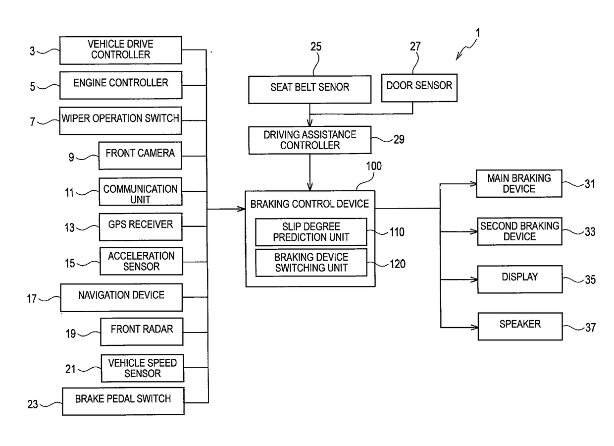
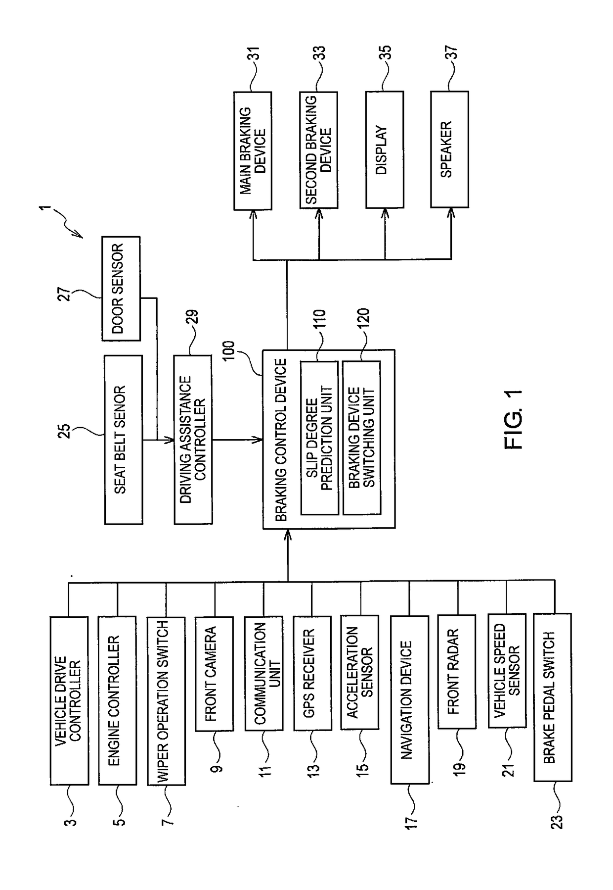
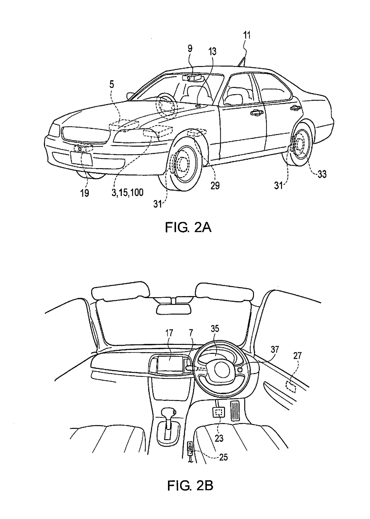
[0023]FIG. 1 is a block diagram illustrating the configuration of a braking control system equipped with the braking control device according to the present embodiment. FIG. 2 is a view illustrating the arrangement on the vehicle of the braking control system according to the present embodiment. The braking control system 1 according to the present embodiment comprises a vehicle drive controller 3, an engine controller 5, a wiper operation switch 7, a front camera 9, a communication unit 11, and a GPS receiver 13, as shown in FIG. 1. In addition, the braking control system 1 comprises an acceleration sensor 15, a navigation device 17, a front radar 19, a vehicle speed sensor 21, a brake pedal switch 23, a seat belt sensor 25, and a door sensor 27. Furthermore, the braking control system 1 comprises a driving assistance controller 29, a main braking device 31, a second braking device 33, a display 35, a speaker 37, and a braking control device 100. A braking control system 1 configur...

modified example 1

[0066]In Modified Example 1, the timing with which the braking force of the main braking device 31 falls to or below a predetermined value is delayed, by reducing the speed at which the braking force of the main braking device 31 is decreased, as illustrated in FIG. 9(a). For example, in the case of Level 1, the speed at which the braking force is decreased will be W, which is the same as in a normal state, but when the slip degree increases and becomes Level 2, the speed at which the braking force is decreased is reduced to X. Then, when the slip degree further increases to Levels 3 and 4, the speed at which the braking force is decreased is further reduced from Y to Z. By reducing the speed at which the braking force of the main braking device 31 is decreased in this manner, the timing with which the braking force of the main braking device 31 falls to or below a predetermined value is delayed.

modified example 2

[0067]In Modified Example 2, the timing with which the braking force of the main braking device 31 falls to or below a predetermined value is delayed, by reducing the braking force of the main braking device 31 in a stepwise manner, as illustrated in FIG. 10(a). For example, in the case of Level 1, the braking force is reduced only once in a stepwise manner as indicated by W, but when the slip degree increases and becomes Level 2, the braking force is reduced twice in a stepwise manner as indicated by X. Then, when the slip degree further increases to Levels 3 and 4, the braking force is reduced three times and four times, as indicated by Y and Z, respectively. In this manner, by reducing the braking force of the main braking device 31 in a stepwise manner, the timing with which the braking force of the main braking device 31 falls to or below a predetermined value is delayed.

[0068]As described in detail above, in the braking control device 100 according to the present embodiment, w...


PUM


Abstract

A braking control device is provided to automatically control a main braking device normally used to brake a host vehicle during travel and a second braking device used to maintain the host vehicle in a stopped state. The braking control device has a slip degree prediction unit and a braking device switching unit. The slip degree prediction unit predicts a possibility that the host vehicle will slip. The braking device switching unit is configured to delay a timing with which to start a reduction in a braking force of the main braking device if the slip degree prediction unit predicts a slip when switching the main braking device to the second braking device.

Description

CROSS-REFERENCE TO RELATED APPLICATIONS[0001]This application is a U.S. National stage application of International Application No. PCT / JP2015 / 071257, filed Jul. 27, 2015.BACKGROUNDField of the Invention[0002]The present invention relates to a braking control device and a braking control method for automatically controlling a main braking device normally used to brake a host vehicle during travel and a second braking device used to maintain the host vehicle in a stopped state.Background Information[0003]In a conventional driving assistance system, such as an adaptive cruise control system, control is carried out such that a host vehicle is stopped following deceleration and stopping of a preceding vehicle by automatically controlling a main braking device, which is a hydraulic brake, after which the vehicle is transitioned to a stop holding state. Japanese Laid-Open Patent Application No. 2010-95189 (referred to herein as Patent Document 1) discloses such a conventional travel contr...

Claims


Application Information

Patent Timeline
IPC IPC(8): B60T8/1755B60T8/1761B60W10/184B60W30/17B60W10/18B60T13/66B60T8/48B60T8/24
CPCB60T8/245B60W2550/148B60Y2400/81B60W2600/00B60T8/17552B60T8/17616B60W10/184B60W30/17B60W10/182B60T13/662B60T8/4827B60T2201/10B60T7/12B60T2201/06B60W2552/40B60T2210/12B60W2556/10B60T2210/32B60T8/17B60W10/18B60W30/14B60W2556/00
Inventor TAKAE, YASUHIKOSUGANO, TAKESHI
Owner NISSAN MOTOR CO LTD
Learn More