Building panel intended for creating heating and/or cooling walls of buildings

Active Publication Date: 2018-07-19
KEOKI CO SA
View PDF6 Cites 5 Cited by
  • Summary
  • Abstract
  • Description
  • Claims
  • Application Information

AI Technical Summary

Benefits of technology

[0014]Thus configured, the invention allows a quick and simplified installation of a heating and/or cooling circuit inside a wall of a building, and without having to call on a specialized company. Furthermore, as the panel of the invention can be installed over an existing wall of the building, it is possible to use the solution of the invention within buildings that have been already built.
[0015]In addition, the detection means provided at each panel can immediately detect when a leak occurs and the precise positioning of this leak. Once the leak has been detected, control means can automatically stop the fluid supply system to prevent any a

Problems solved by technology

The disadvantage of this known technique is the need to call on a specialized company to install such circuits.
Furthermore, this technique requires major construction work to integrate said tubes inside the walls.
It is therefore not suitable for buildings that have been already built, in which the tubes should be integrated into existing walls.
Additionally, this known technique has a major disadvantage in case of leakage of heat-carrying fluid or coolant.
Indeed, because of the generally long time separating the occurrence of the leak and its detection by the occupants of the building, this type of leakage often results in a significant degradation of the wall and of the building in general, which has the consequence of overly increasing the costs of the repair work afterwards.
Moreover, once the leak is detected, it is very difficult for the repairer, given the difficulty of accessing the tubes hidden inside the walls of buildings, on the one hand to know where the leak is and, on the other hand, to quickly and simply replace the faulty tube or tubes.
It is therefore often neces

Method used


Image

  • Building panel intended for creating heating and/or cooling walls of buildings
  • Building panel intended for creating heating and/or cooling walls of buildings
  • Building panel intended for creating heating and/or cooling walls of buildings

Examples


Embodiment Construction

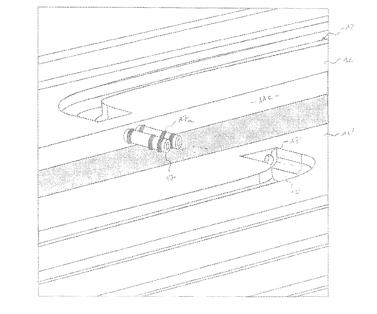
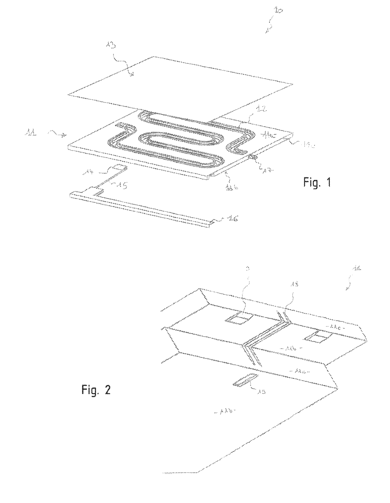
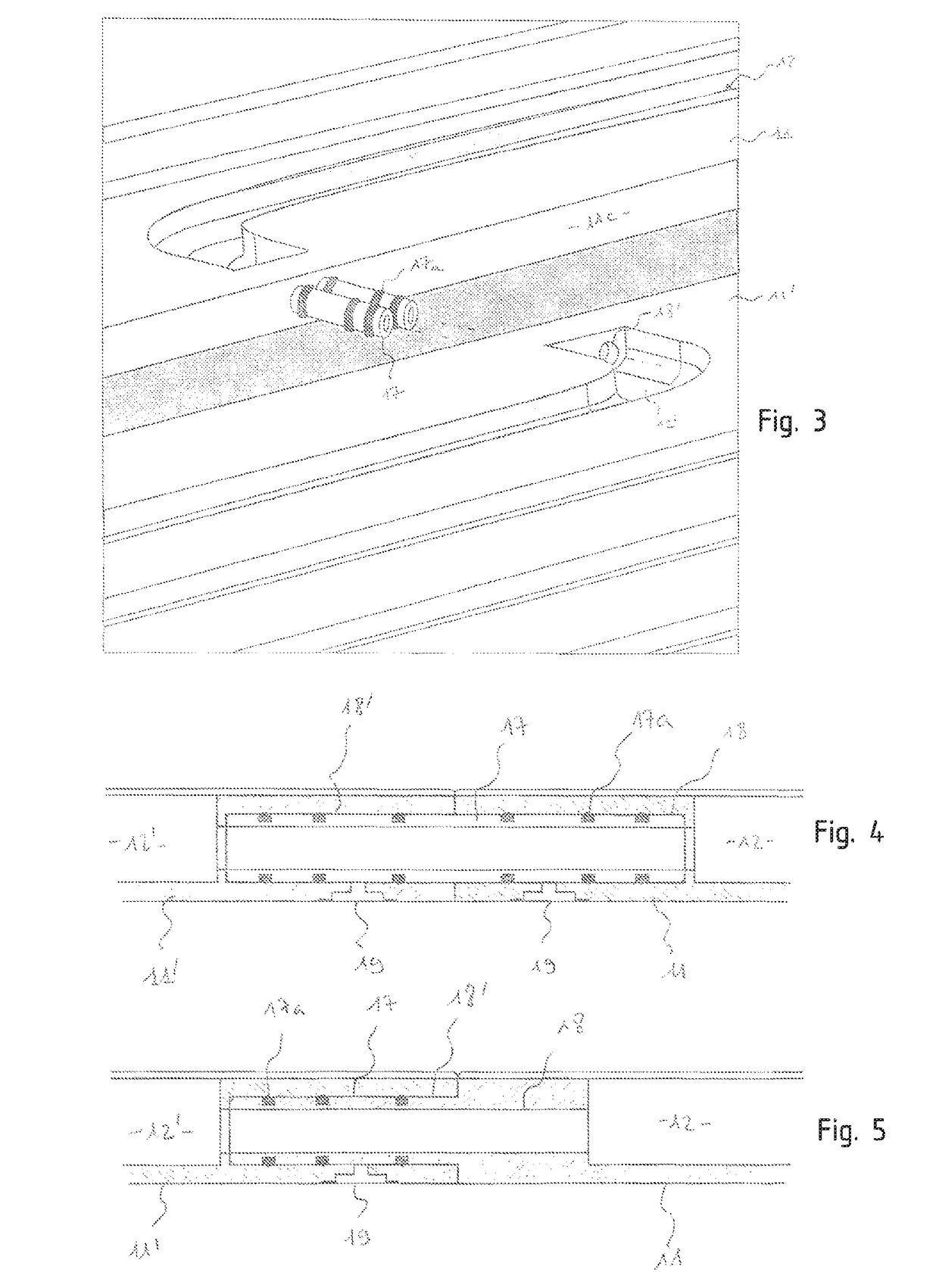
[0031]With reference to FIG. 1, a building panel according to the present invention is shown. This building panel comprises in particular a base element 11 in the form of a substantially rectangular plate of a certain thickness, said plate being defined by its upper face 11a, its lower face 11b and its four lateral faces 11c. The base element 11 will preferably be formed by molding an insulating and flame retardant thermoplastic resin. During the formation of the base element 11, channels 12 have been made at the upper surface 11a, said channels being configured to allow the circulation of a heat-carrying fluid or coolant through the panel. The channels 12 will advantageously be arranged so as to at least partially cover the surface of the base element, thus allowing a homogeneous distribution of heat or cold through the panel. Thus, in one of the possible arrangements shown in FIG. 1, the channels 12 define a coil shape.

[0032]The panel also comprises a conductive element 13 in the ...


PUM


Abstract

The invention relates to a building panel intended for creating heating and/or cooling walls of buildings, comprising: a base element defined by an upper face, a lower face and several lateral faces circulation means (12) for the circulation of a heat-transfer or cooling fluid, which are arranged on the inside of said base element, a substantially flat conducting element, fixed to the upper face of the base element so as to cover it entirely or almost entirely, said conducting element having good thermal conductivity, mechanical connection means secured to said base element, said mechanical connection means being able to allow removable attachment of said building panel to an identical or similar building panel arranged adjacent to the latter, fluidic-connection means designed to allow the heat-transfer or cooling fluid to circulate between said building panel and an identical or similar building panel attached thereto, leak detection means able to detect a leak of heat-transfer or cooling fluid at the lower or upper face of the base element.

Description

TECHNICAL FIELD[0001]The present invention relates to a prefabricated modular building panel for producing heating and / or cooling walls of buildings wherein said panel incorporates a technical circuit and a finish making it possible to achieve a very thin thickness. It also relates to a wall formed by the rapid assembly of such panels, as well as a supply system for heat-carrying fluid or coolant designed to be connected to a heating and / or cooling circuit formed within said wall.STATE OF THE ART[0002]In the field of heating and / or cooling of buildings, it is known to integrate heating and / or cooling circuits inside panels, such as floors, walls or ceilings. Such heating circuits generally consist of an array of tubes inside which a heat-carrying fluid or coolant flows. The disadvantage of this known technique is the need to call on a specialized company to install such circuits. Furthermore, this technique requires major construction work to integrate said tubes inside the walls. I...

Claims


Application Information

Patent Timeline
IPC IPC(8): F24D3/14E04C2/52F24D3/12F24F5/00
CPCF24D3/142E04C2/525F24D3/125F24F5/0089E04B5/48E04B9/001F24D3/165Y02B30/00E04C2/52F24D3/16
Inventor BARATTI, ALBERTOBOCCIOLONE, FAUSTOCASSETTA, PAOLO
Owner KEOKI CO SA
Why Eureka
Try Eureka