
Measuring device and method for measuring at least one length measurand

a technology of measuring device and length measurand, which is applied in the direction of measuring device, using optical means, instruments, etc., can solve the problem that the measuring frame does not support any for

Inactive Publication Date: 2018-07-19
CARL MAHR HLDG
View PDF5 Cites 9 Cited by
  • Summary
  • Abstract
  • Description
  • Claims
  • Application Information

AI Technical Summary

Benefits of technology

The present invention relates to a measurement device and method that enables highly precise length measurements. The invention includes a measuring frame that is immovably connected to a machine base and made of a material insensitive to temperature changes. The invention also includes interferometer arrangements that emit multiple laser measuring beams in different directions and receive them reflected from the reflectors. The position of the probe unit or carrier part can be determined in a further spatial direction relative to the reflectors or machine base. The use of six reflectors and laser measuring beams in all directions provides even higher precision.

Problems solved by technology

However, the measuring beam of the interferometer does not run at the location at which the refractometer measures the refractive index.
The measuring frame does not support any forces caused by the measuring device or the workpiece.

Method used


Image

  • Measuring device and method for measuring at least one length measurand
  • Measuring device and method for measuring at least one length measurand
  • Measuring device and method for measuring at least one length measurand

Examples


Embodiment Construction

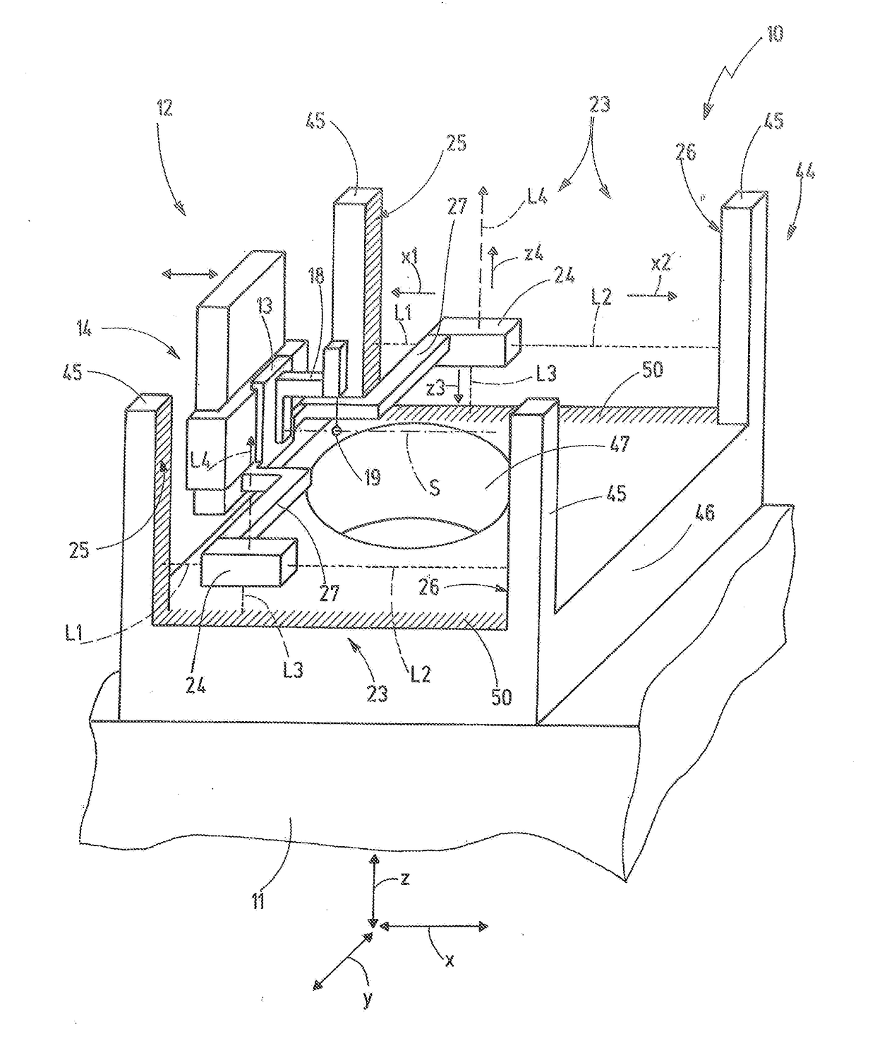
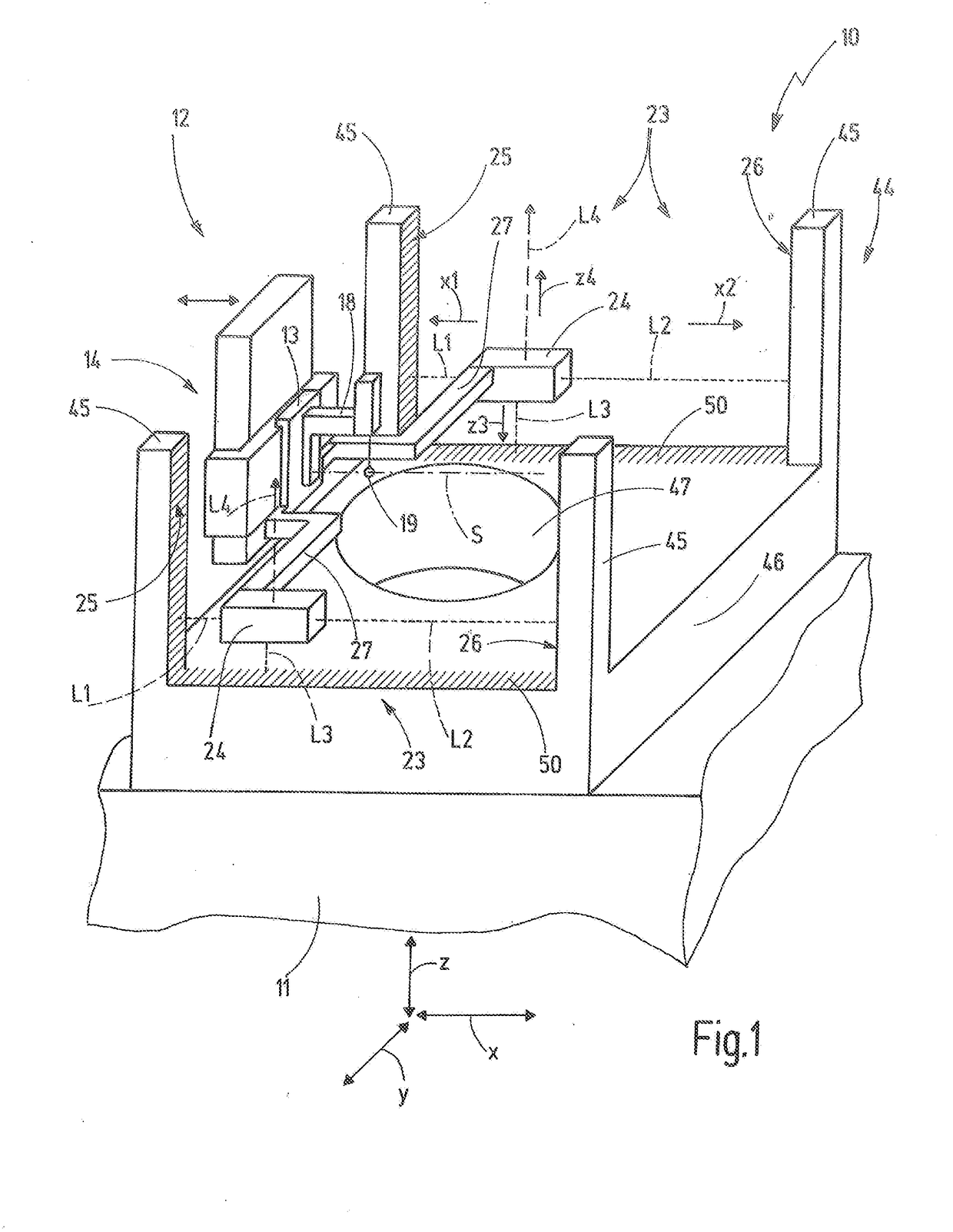
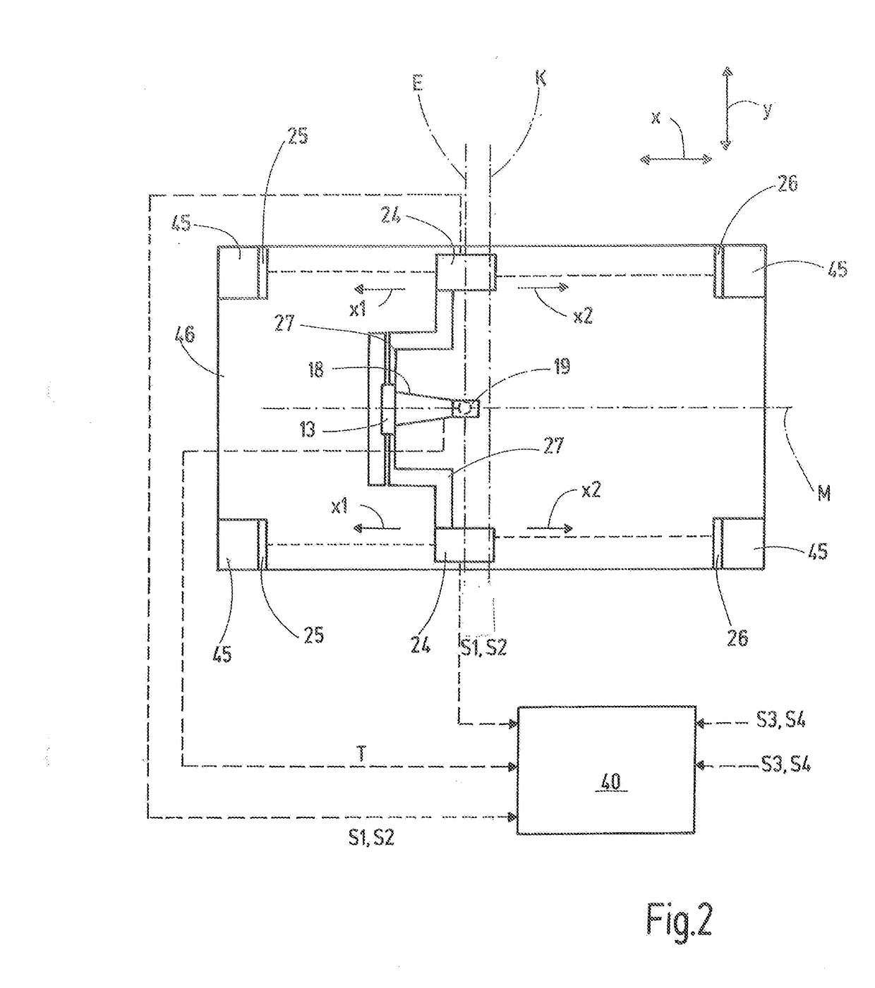
[0035]FIGS. 1-3 show exemplary embodiments of a measuring device 10. The measuring device 10 has a machine base 11, which is used to support the measuring device 10 on a substrate surface. The machine base 11 for example can be a machine frame or a cast body.

[0036]A positioning arrangement 12 is provided on the machine base 11. The positioning arrangement 12 is used to move and position a carrier part 13 in at least one degree of freedom relative to the machine base 11. The carrier part 13 for example can be moved or positioned relative to the machine base 11 in three linear degrees of freedom by means of a slide arrangement 14. The positioning arrangement 12 for this purpose has corresponding drives. The positioning arrangement 12 can also have rotary guides and drives. The carrier part 13 can be movable in up to six degrees of freedom. The number of the linear degrees of freedom and the rotary degrees of freedom is arbitrary. In the exemplary embodiment illustrated here, the carri...


PUM


Abstract

The invention relates to a measuring device (10) and a method for determining a length measurand of a workpiece. A carrier part (13), on which a probe unit (18) is arranged immovably in a first spatial direction (x), can be moved or positioned by means of a positioning arrangement (12). At least one laser interferometer (24) is connected to the carrier part (13) immovably in the first spatial direction (x). By means of a first laser measuring beam (L1) and a second laser measuring beam (L2), the laser interferometer (24) generates a first measurement signal (S1), which measurement signal describes the distance of the laser interferometer (24) from a first reflector (25) in the first spatial direction (x), and a second measurement signal (S2), which describes the distance of the laser interferometer (24) from a second reflector (26) in the first spatial direction (x). A probe system plane (E), which is immovable in the first spatial direction (x) relative to the carrier part (13) or the probe unit (18) and which extends at right angles to this first spatial direction (x), therefore has a position in the first spatial direction (x) that can be determined by means of the distances of the laser interferometer (24) from the first reflector (25) and the second reflector (26).

Description

CROSS-REFERENCE TO RELATED APPLICATIONS[0001]This application claims all benefits provided by law including benefit of priority under 35 U.S.C. § 119 to German Patent Application No. 10 2017 100 991.4 filed Jan. 19, 2017, the content of which is hereby incorporated by reference in its entirety.STATEMENT REGARDING FEDERALLY SPONSORED RESEARCH[0002]Not ApplicableREFERENCE TO MICROFICHE APPENDIX[0003]Not ApplicableBACKGROUNDTechnical Field of the Invention[0004]The invention relates to a measuring device and a method for measuring at least one length measurand at a workpiece. The measuring device for this purpose has a probe unit which can probe the workpiece with mechanical contact or contactlessly, for example optically, in order to measure the length measurand. For example, outer diameters, inner diameters, contours, etc. of the workpiece can be measured.Description of the Prior Art[0005]DE 1588 018 B2 discloses a device for positioning a cross slide. The device works with an optica...

Claims


Application Information

Patent Timeline
IPC IPC(8): G01B11/02G01B9/02
CPCG01B11/02G01B9/02015G01B11/12G01B11/002G01B5/008G01B5/0014G01B9/02021G01B9/02027
Inventor ZIEGENBEIN, RAINER
Owner CARL MAHR HLDG
Learn More