
Casting mold, and production method thereof

a technology of molds and molds, applied in the field of casting molds, can solve the problems of increasing the area between the molten metal and the coating (carbon film), increasing the frictional force, and reducing the heat insulation property between the mold and the molten metal, so as to maintain the liquidity of the molten metal and control the exfoliation of the coating

Active Publication Date: 2018-07-26
HONDA MOTOR CO LTD
View PDF0 Cites 1 Cited by
  • Summary
  • Abstract
  • Description
  • Claims
  • Application Information

AI Technical Summary

Benefits of technology

The present invention provides a casting mold and a production method that can control the exfoliation of the coating and maintain the liquidity of the molten metal. By controlling the surface texture of the mold and the penetration rate of the molten metal, the likelihood of the coating to exfoliate from the groove part is minimized. This results in improved surface quality of the casted metal.

Problems solved by technology

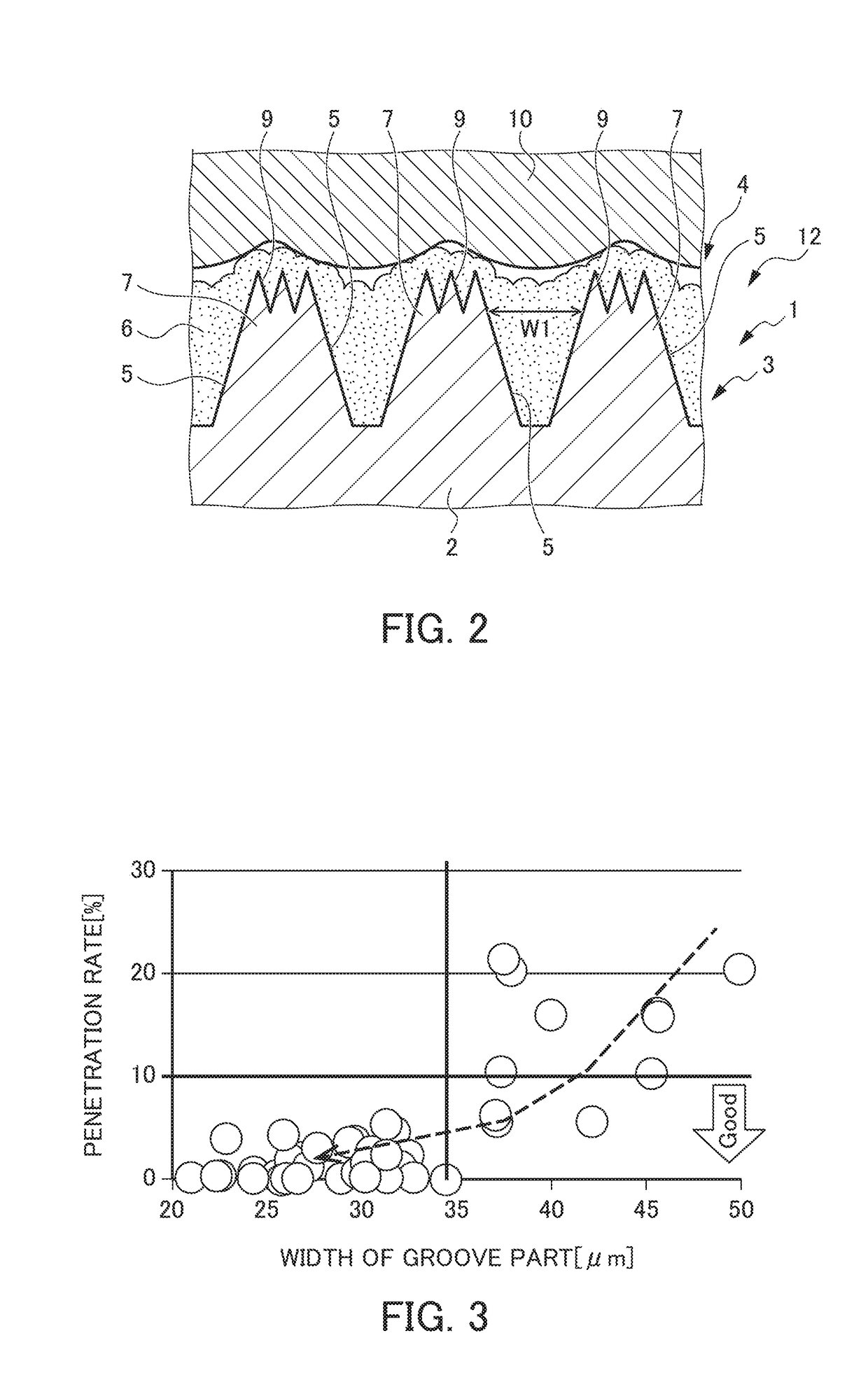
When the penetration rate of this molten metal (rate of molten metal in the volume of the groove part) becomes high, the contact area between the molten metal and the coating (carbon film) is increased and frictional force is increased, and there is a possibility that the coating (carbon film), which is a heat insulation layer, exfoliates from the groove part.
When the coating exfoliates, the heat insulation property between the mold and the molten metal is decreased, and the liquidity of the molten metal cannot be improved.

Method used


Image

  • Casting mold, and production method thereof
  • Casting mold, and production method thereof
  • Casting mold, and production method thereof

Examples


Embodiment Construction

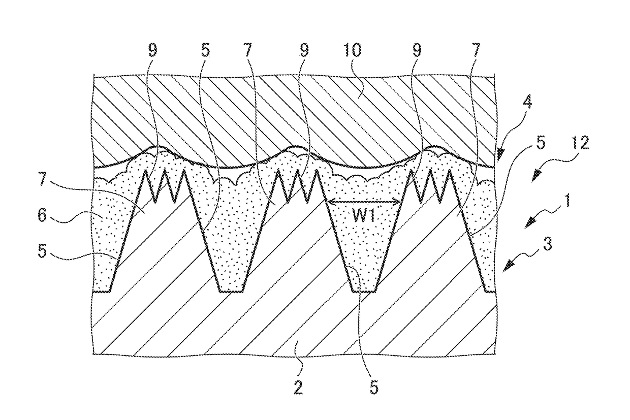
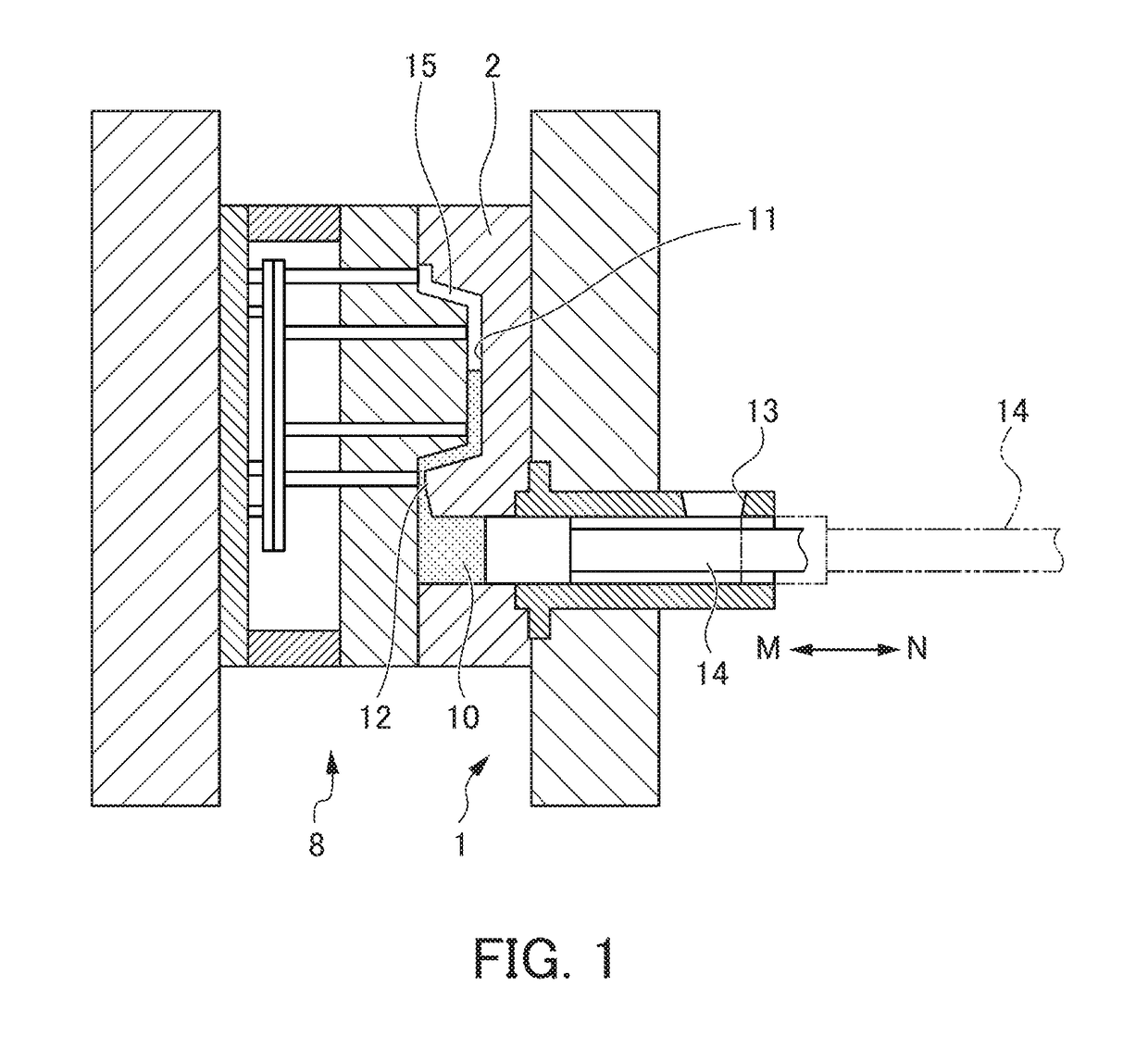
[0020]In the following, an example of an embodiment of the present invention will be described. FIG. 1 is a sectional view illustrating an injection process in an aluminum casting process using a casting mold according to the embodiment of the present invention. FIG. 2 is a schematic sectional view illustrating a surface processing part of the casting mold according to the embodiment of the present invention.

[0021]A casting mold 1 according to the embodiment is for casting aluminum 10 into a desired shape in cooperation with a male mold 8, as illustrated in FIG. 1. This casting mold 1 includes a mold material 2, and the mold material 2 includes a product part 11 and a plan part 12. As illustrated in FIG. 2, a surface processing part 3 is formed in the molten metal contact part of the plan part 12 (the part where casting mold 1 is in contact with the molten metal). In this surface processing part 3, a plurality of tapered groove parts 5 is coated with a carbon film 6. These groove pa...


PUM

PropertyMeasurementUnit
surface roughnessaaaaaaaaaa
widthaaaaaaaaaa
width W1aaaaaaaaaa

Abstract

A casting mold and a production method thereof with which exfoliation of coating is controlled and liquidity of molten metal can be maintained are provided. This casting mold 1 includes a surface processing part 3 in which a plurality of groove parts 5 of a grid groove 4 formed in a surface of a molten metal contact part of a mold material 2 is coated with a carbon film 6. In this surface processing part 3, a width W1 of the groove parts 5 is 35 μm or narrower, skewness Ssk of three-dimensional surface roughness is in a range of −0.8 to −0.2, and indentation hardness of the carbon film 6 tested by a nanoindenter is 1000 N / mm2 or higher. With this arrangement, it is possible to optimize the surface processing part 3 in such a manner that a penetration rate of the molten metal (aluminum 10) is controlled to be low and the coating (carbon film 6) is unlikely to exfoliate from the groove parts 5.

Description

[0001]This application is based on and claims the benefit of priority from Japanese Patent Application No. 2017-011169, filed on 25 Jan. 2017, the content of which is incorporated herein by reference.BACKGROUND OF THE INVENTIONField of the Invention[0002]The present invention relates to a casting mold, and a production method thereof.Related Art[0003]Generally, in a case where metal is cast into a desired shape, it is important, for example, in a die-cast mold that liquidity in the plan part (part from the plunger part, from which molten metal is supplied, to the cavity) and in the cavity thereof is improved in such a manner that molten metal (such as aluminum) poured into the mold quickly and smoothly fills the whole area in the cavity with a predetermined molten metal temperature being maintained.[0004]Thus, an applicant has proposed a technology for improving the liquidity of molten metal by reducing the contact area between the molten metal and the mold surface by forming a plur...

Claims


Application Information

Patent Timeline
Patent Type & Authority Applications(United States)
IPC IPC(8): B22C3/00B22D18/04B22D21/00B22C9/06B23K26/364
CPCB22C3/00B22D18/04B22D21/007B22C9/06B23K26/364B22D17/22B23K26/36B22D21/04
Inventor GOTO, MINORUYUKI, KENJISAKAMOTO, SATOSHIFUJITA, TAKASHI
Owner HONDA MOTOR CO LTD
Learn More