
Magnetic core with flexible packaging

Active Publication Date: 2018-08-02
CUMMINS INC
View PDF3 Cites 0 Cited by
  • Summary
  • Abstract
  • Description
  • Claims
  • Application Information

AI Technical Summary

Benefits of technology

The present patent provides a magnetic core that can be securely closed and opened for the passage of wires. The core is enclosed in a flexible package with a gap between the package and the core. A clamp is attached to the package to secure the core in the closed position. A movable member is coupled to the package to allow wires to pass through the gap and enter the central opening, while preventing them from coming out. The core is made of flexible material, such as magnetic tape or flexible magnetic material. The package is made of rubber or plastic. The gap between the package and the core is sealed with a protective material. The technical effects of this invention include improved protection of the core from environmental conditions, easy assembly, and flexibility in wire passage.

Problems solved by technology

If one core fails in this application, then the entire twisted wire assembly must be disassembled to the extent necessary to remove and replace the failed core.
This repair procedure is time consuming and therefore expensive.
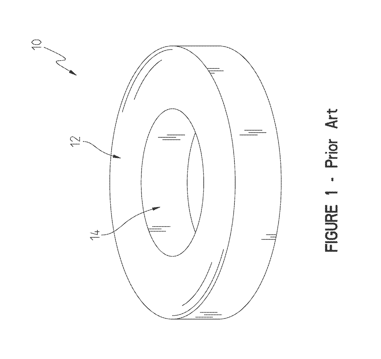
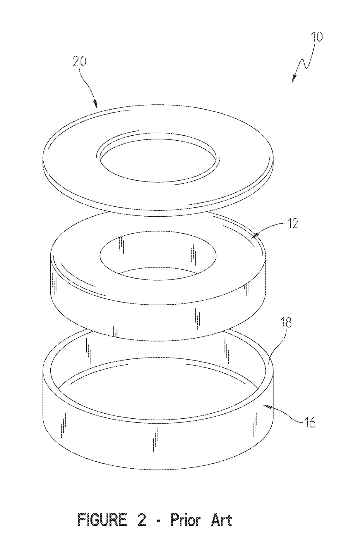
These gaps cause low permeability (also called magnetic permeability) of core 40 and increased core losses, which may be undesirable characteristics when compared to a solid core of the same size and shape depending upon the electromagnetic needs of the electrical application.
This also leads to undesirable performance characteristics.

Method used


Image

  • Magnetic core with flexible packaging
  • Magnetic core with flexible packaging
  • Magnetic core with flexible packaging

Examples


first embodiment

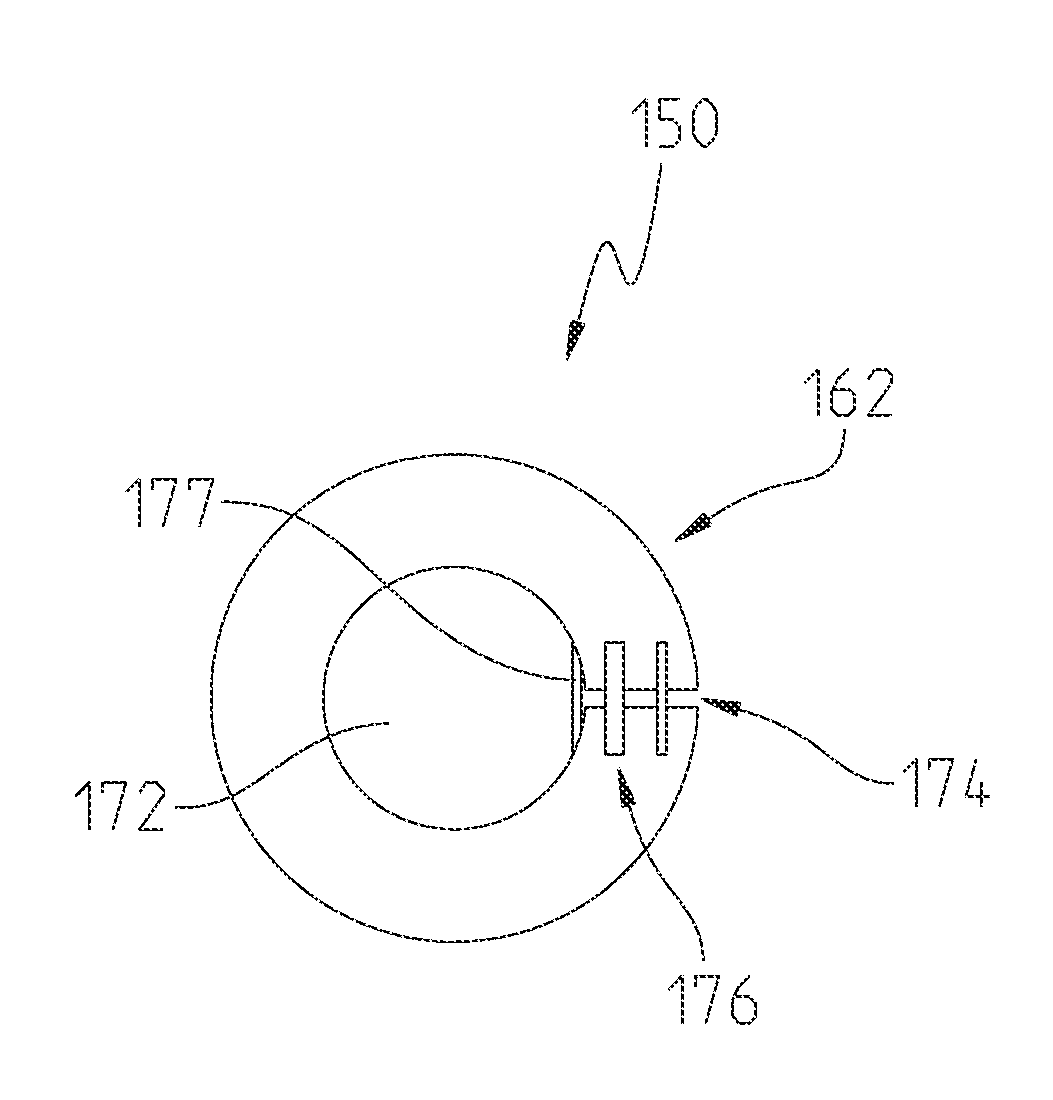
[0025]FIGS. 5(A)-(D) depict a core according to the principles of the present disclosure. Core 150 includes a body 152 (FIG. 5(B)), which may be formed in the shape of a toroid or cylinder, made by winding material, for example, of the type and in the manner described above with reference to FIGS. 1-3. In certain embodiments, the material is vitreous material or a flexible magnetic material. Body 152 includes an outer surface 154, an inner surface 156, a first side surface 158 and a second side surface 160 (not shown). Body 152 is encased within a package 162 (FIG. 5(A)), which may be formed of rubber, plastic or other suitable flexible material. Package 162 includes an outer surface 164, an inner surface 166, a first side surface 168 and a second side surface 170 (not shown). Inner surface 166 of package 162 defines a central opening 172 for receiving a wire or wires such as in the twisted pair application described above.

[0026]As shown in FIG. 5(C), in one embodiment after body 15...

second embodiment

[0031]Referring now to FIGS. 6(A)-(D), a core according to the principles of the present disclosure is shown. Core 250 (FIG. 6(B)) includes a body 252 made by winding material, for example, of the type and in the manner described above with reference to FIG. 3. Body 252 includes an outer surface 254, an inner surface 256, a first side surface 258 and a second side surface 260 (not shown). Body 252 is encased within a partially rubber based package 262 (FIG. 6(A)). Package 262 includes flexible portion 253 (which in one embodiment is rubber based) and an epoxy or plastic portion 255 which adds to the strength of core 250. Flexible portion 253 acts as a hinge as is described below. Package 262 further includes an outer surface 264, an inner surface 266, a first side surface 268 and a second side surface 270 (not shown). Inner surface 266 of package 262 defines a central opening 272 for receiving a wire or wires such as in the twisted pair application described above.

[0032]As shown in ...


PUM


Abstract

The disclosure provides a core, comprising a body formed from a winding of tape shaped material, and a package encasing the body. A single gap is formed in the body and the package. A clamp is connected to the package to flex a flexible section of the package to reduce the gap.

Description

RELATED APPLICATIONS[0001]The present application is based on and claims priority to U.S. Provisional Application Ser. 62 / 084,168, entitled “MAGNETIC CORE WITH FLEXIBLE PACKAGING,” filed on Nov. 25, 2014, the entire contents of which being expressly incorporated herein by reference.TECHNICAL FIELD[0002]The present disclosure relates generally to magnetic cores and more particularly to magnetic cores having a single gap and flexible packaging.BACKGROUND OF THE DISCLOSURE[0003]Magnetic cores are available in a variety of shapes and sizes. Generally, magnetic cores have magnetic material inside such as soft iron, laminated silicon steel, carbonyl iron, iron powder, ferrite and vitreous material. These cores may be formed into shapes such as air cores, straight cylindrical rods, tape wound cores, alphabet letter shaped cores (I, E, C, U, E-I, paired E, E-P, EFD, E-R, etc.), pot cores, toroid cores, rings or bead cores, and planar cores. Applications for such cores include, but are not l...

Claims


Application Information

Patent Timeline
IPC IPC(8): H01F3/04H01F17/06H01F27/02H01F3/14H01F41/02
CPCH01F3/04H01F17/062H01F27/02H01F3/14H01F41/022H01F2017/065H01F17/06
Inventor PANDEY, NIKHILBECKER, PHILIP E.GONZALEZ, JR., MIGUEL ANGELDE, ANIRBAN
Owner CUMMINS INC
Learn More