Display system, wireless power transmission apparatus, and wireless power reception apparatus

a technology of wireless power transmission and display system, which is applied in the direction of static indicating devices, instruments, transportation and packaging, etc., can solve the problems of power wires exposed and the inability to position coils with a wide width in the display apparatus, and achieve the effect of minimizing the leakage magnetic field

Inactive Publication Date: 2018-08-02
SAMSUNG ELECTRONICS CO LTD
View PDF5 Cites 19 Cited by
  • Summary
  • Abstract
  • Description
  • Claims
  • Application Information

AI Technical Summary

Benefits of technology

[0028]According to aspects of one or more exemplary embodiments, a wall-mountable display system may be installed without exposed power wires and power may be wirelessly transmitted and received while minimizing a leakage magnetic field of front and rear sides.

Problems solved by technology

Most wall-mountable TVs are positioned on an upper wall spaced apart from a table and, thus, a problem occurs in that power wires are exposed.
However, in consideration of recent trends in which a display apparatus has become more slim, a problem occurs in that it is not possible to position a coil with a wide width in the display apparatus.
Also, an exemplary embodiment is not required to overcome the disadvantages described above, and an exemplary embodiment may not overcome any of the problems described above.

Method used


Image

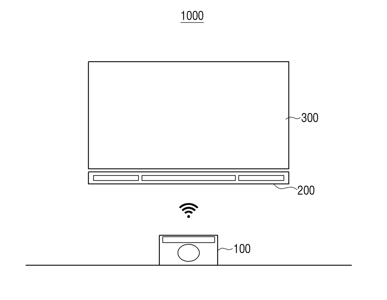
  • Display system, wireless power transmission apparatus, and wireless power reception apparatus
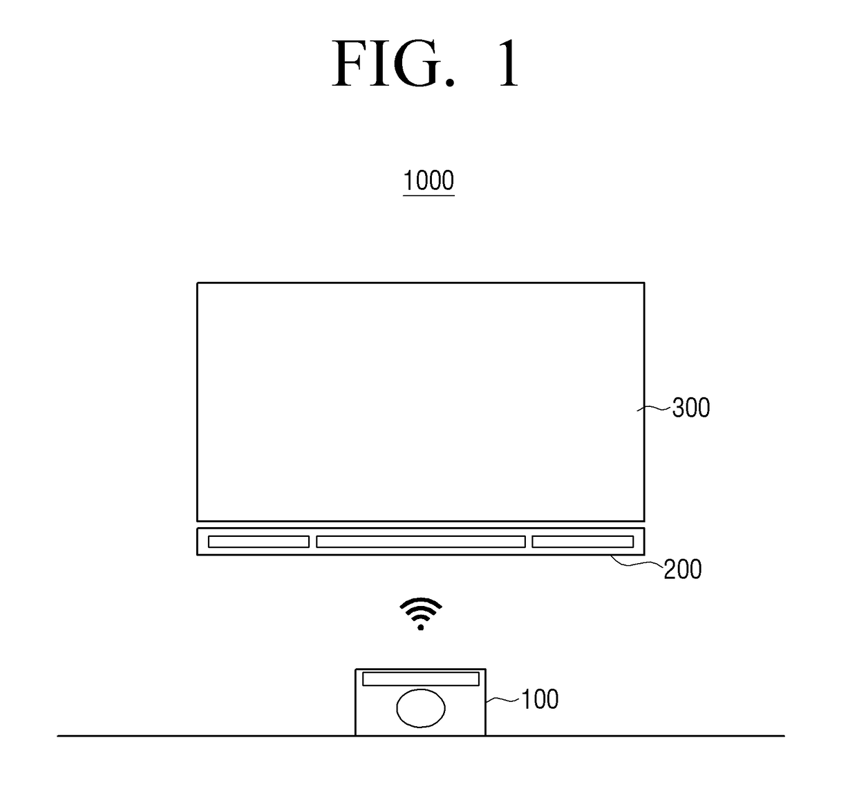
  • Display system, wireless power transmission apparatus, and wireless power reception apparatus
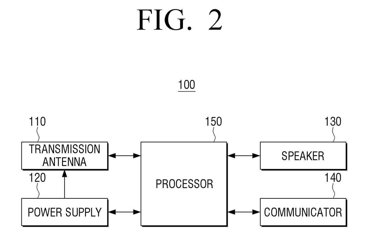
  • Display system, wireless power transmission apparatus, and wireless power reception apparatus

Examples


Embodiment Construction

[0040]Certain exemplary embodiments will now be described in greater detail with reference to the accompanying drawings. In the following description, a detailed description of known functions and configurations incorporated herein will be omitted when it may make the subject matter of the present disclosure unclear. The terms used in the specification are defined in consideration of functions used in the present disclosure, and can be changed according to the intent or typically used methods of clients, operators, and users. Accordingly, definitions of the terms should be understood on the basis of the entire description of the present specification.

[0041]It will be understood that, although the terms first, second, third, etc., may be used herein to describe various elements, these elements should not be limited by these terms. These terms are only used to distinguish one element from another element. For example, a first element may be termed a second element and a second element...


PUM


Abstract

A display system, a wireless power transmission apparatus, and a wireless power reception apparatus are provided. The display system includes a wireless power transmission apparatus, a wireless power reception apparatus, and a display apparatus configured to receive power from the wireless power reception apparatus, wherein the wireless power transmission apparatus includes a first coil and a second coil of a closed loop arranged above the first coil and configured to apply power to the first coil to generate a magnetic field in a direction toward the wireless power reception apparatus, and wherein, in response to the generated magnetic field being applied to the wireless power reception apparatus, the wireless power reception apparatus is configured to generate power using a coil of a multilayer structure into which a plurality of insulators is inserted and to transmit the generated power to the display apparatus.

Description

CROSS-REFERENCE TO RELATED APPLICATION[0001]This application claims priority from Korean Patent Application No. 10-2017-0014491, filed on Feb. 1, 2017 in the Korean Intellectual Property Office, the disclosure of which is incorporated herein by reference in its entirety.BACKGROUNDField[0002]Apparatuses and methods consistent with one or more exemplary embodiments relate to a display system, a wireless power transmission apparatus, and a wireless power reception apparatus, and more particularly, to a display system, a wireless power transmission apparatus, and a wireless power reception apparatus, for wirelessly transmitting and receiving power without an adverse effect on a design.Description of the Related Art[0003]To effectively use a living space, the number of users that desire a display apparatus in the form of a wall-mountable television (TV) has increased. Most wall-mountable TVs are positioned on an upper wall spaced apart from a table and, thus, a problem occurs in that pow...

Claims


Application Information

Patent Timeline
Patent Type & Authority Applications(United States)
IPC IPC(8): H02J50/12H02J7/02H02J5/00H02J50/40H02J50/50H02J50/70
CPCH02J50/12H02J50/40H02J50/70H02J5/005H02J50/50H02J7/025H02J50/20H01F27/28H01F38/14H04B5/0037H02J7/0042H01F27/38G09G2330/00H02J50/502
Inventor CHOI, YOUNG-HOLIM, SANG-MINLEE, KYU-SUNG
Owner SAMSUNG ELECTRONICS CO LTD
Why Eureka
Try Eureka