
Light emitting device for generating light with embedded information

a technology of embedded information and light emitting device, which is applied in the direction of electromagnetic transmission, transmission, close-range type systems, etc., can solve problems such as positioning problems or control problems, and achieve the effects of improving signal/noise ratio, improving signal/noise ratio, and seeing the effect area more clearly

Active Publication Date: 2018-08-02
SIGNIFY HLDG BV
View PDF48 Cites 6 Cited by
  • Summary
  • Abstract
  • Description
  • Claims
  • Application Information

AI Technical Summary

Benefits of technology

The present invention aims to improve the accuracy and communication between a device emitting a coded beam of light and a receiving device. It introduces new communication paradigms and offers the ability to adjust the color of the light emission based on the shape of the beam. This may enhance the signal to noise ratio, making it easier for users to see the effect area or improve their overall visual experience.

Problems solved by technology

Inaccurate information communication may further lead to either positioning problems or control problems.

Method used


Image

  • Light emitting device for generating light with embedded information
  • Light emitting device for generating light with embedded information
  • Light emitting device for generating light with embedded information

Examples


Embodiment Construction

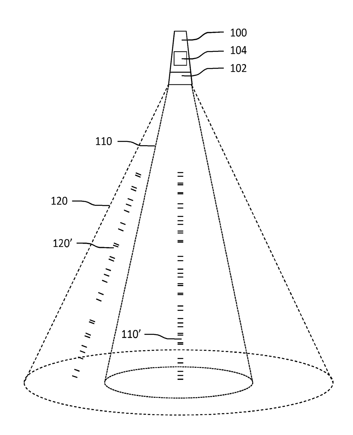
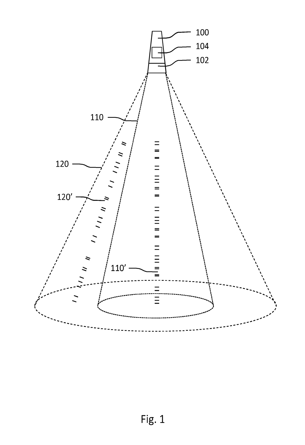
[0036]FIG. 1 shows schematically an embodiment of a light emitting device 100 according to the invention. The light emitting device 100 is arranged for emitting a beam of light, which light emission comprising an embedded code. The embedded code comprises a message for a receiving device, which message may comprise, for example, location related information, indoor position information, control commands, etc. The light emitting device 100 comprises a beam shape controller 102 arranged for controlling a shape of the beam of light emitted by the light emitting device 100. The light emitting device 100 further comprises first processor 104 (such as a micro controller) connected to the beam shape controller, arranged for generating the embedded code. The first processor 104 is further arranged for embedding the message in the embedded code based on the shape of the beam of light emitted by the light emitting device 100. The embedded code may be created by controlling a time-varying, mod...


PUM


Abstract

A light emitting device (100) for emitting a beam of light is disclosed. The light emission of the light emitting device (100) comprises an embedded code. The light emitting device (100) comprises a beam shape controller (102) for controlling a shape of the beam of light and a first processor connected to the beam shape controller, arranged for generating the embedded code. The first processor (104) is further arranged for embedding a message in the embedded code based on the shape of the beam of light. This allows the light emitting device (100) to communicate information to a receiving device based on its effect area (i.e. the illuminated area). This information may, for example, comprise information about the beam shape and size, which may be used to determine an area wherein the receiving device is located relative to the light emitting device (100).

Description

FIELD OF THE INVENTION[0001]The invention relates to a light emitting device for generating an embedded code comprised in the light emission of the light emitting device. The invention further relates to a system for generating and detecting an embedded code comprised in the light emission of a light emitting device. The invention further relates to a method of generating an embedded code comprised in the light emission of a light emitting device.BACKGROUND[0002]Home, public and professional environments may contain a large number of lighting devices comprising light sources, such as light-emitting diodes (LEDs), with the capability of transmitting information by means of coding its light output. One application of such a lighting device is to provide control functionality by communicating information comprising control commands to further devices. Another application, as disclosed in U.S. Pat. No. 7,123,159B2, is to provide position information via coded light to handheld or wearab...

Claims


Application Information

Patent Timeline
IPC IPC(8): H04B10/116H01L33/54H05B37/02H04B10/114H05B33/08H05B44/00
CPCH04B10/116H01L33/54H05B37/0272H04B10/1149H05B33/0896H04B10/1141H05B47/195H05B45/60
Inventor TSANG, PETER TJIN SJOE KONGRAJAGOPALAN, RUBENBROERS, HARRY
Owner SIGNIFY HLDG BV
Learn More