A Nailing Machine

a nailing machine and nailing technology, applied in the field of machine manufacturing, can solve the problems of limiting the movement of the striker, and achieve the effect of reducing the volume and weight of the nailing machine, continuous and efficient firing

Active Publication Date: 2018-08-09
ZHANG HUADING
View PDF0 Cites 7 Cited by
  • Summary
  • Abstract
  • Description
  • Claims
  • Application Information

AI Technical Summary

Benefits of technology

[0005]One objective of one embodiment of the present invention addresses the above problems of the prior art, a nailing machine is provided. The technical problem to be solved b

Problems solved by technology

After the first piston reaches the extreme point, the pawl and the locking pa

Method used


Image

  • A Nailing Machine
  • A Nailing Machine
  • A Nailing Machine

Examples


Embodiment Construction

[0026]The embodiments of this invention will be described below and the technical solutions of the invention will be further illustrated in connection with the accompanying figures. However, the present invention shall not be limited to these embodiments.

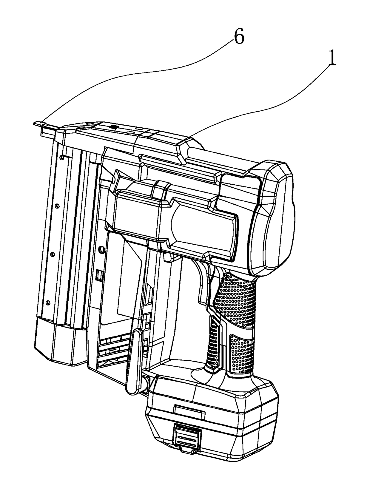
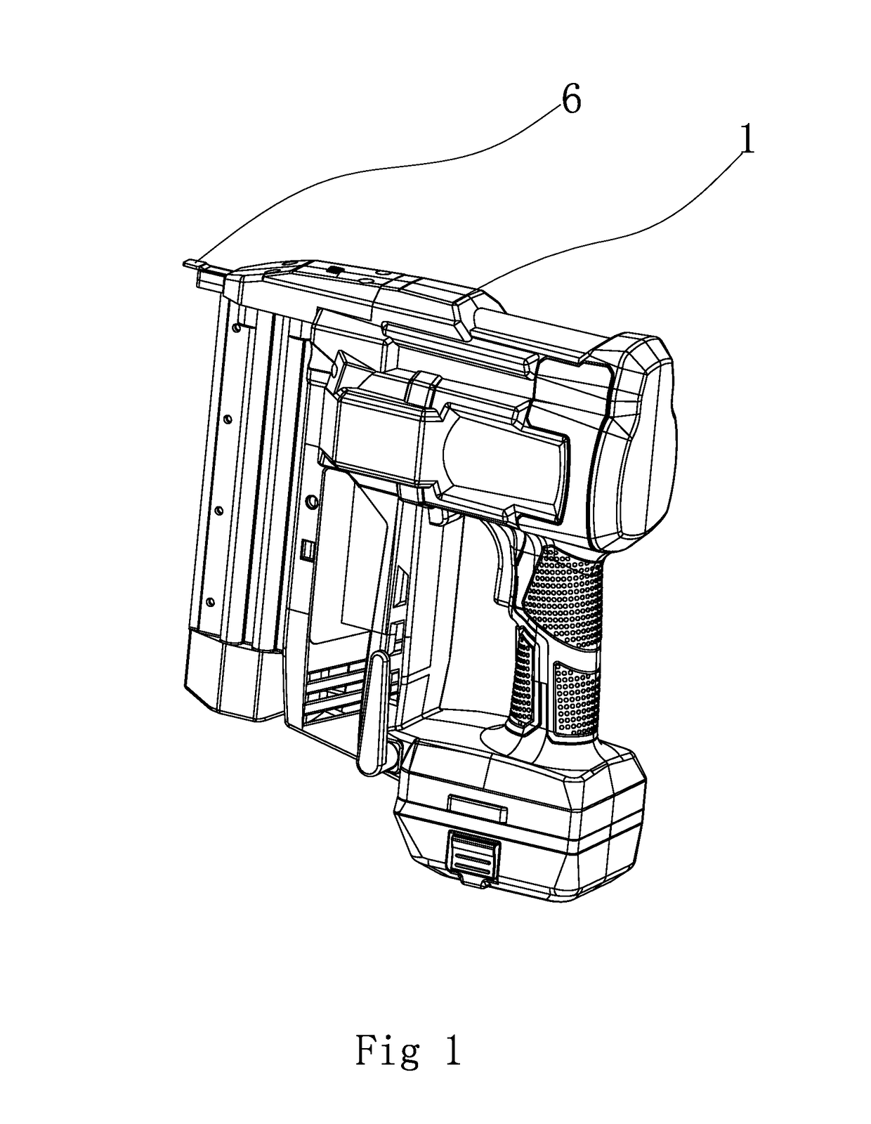
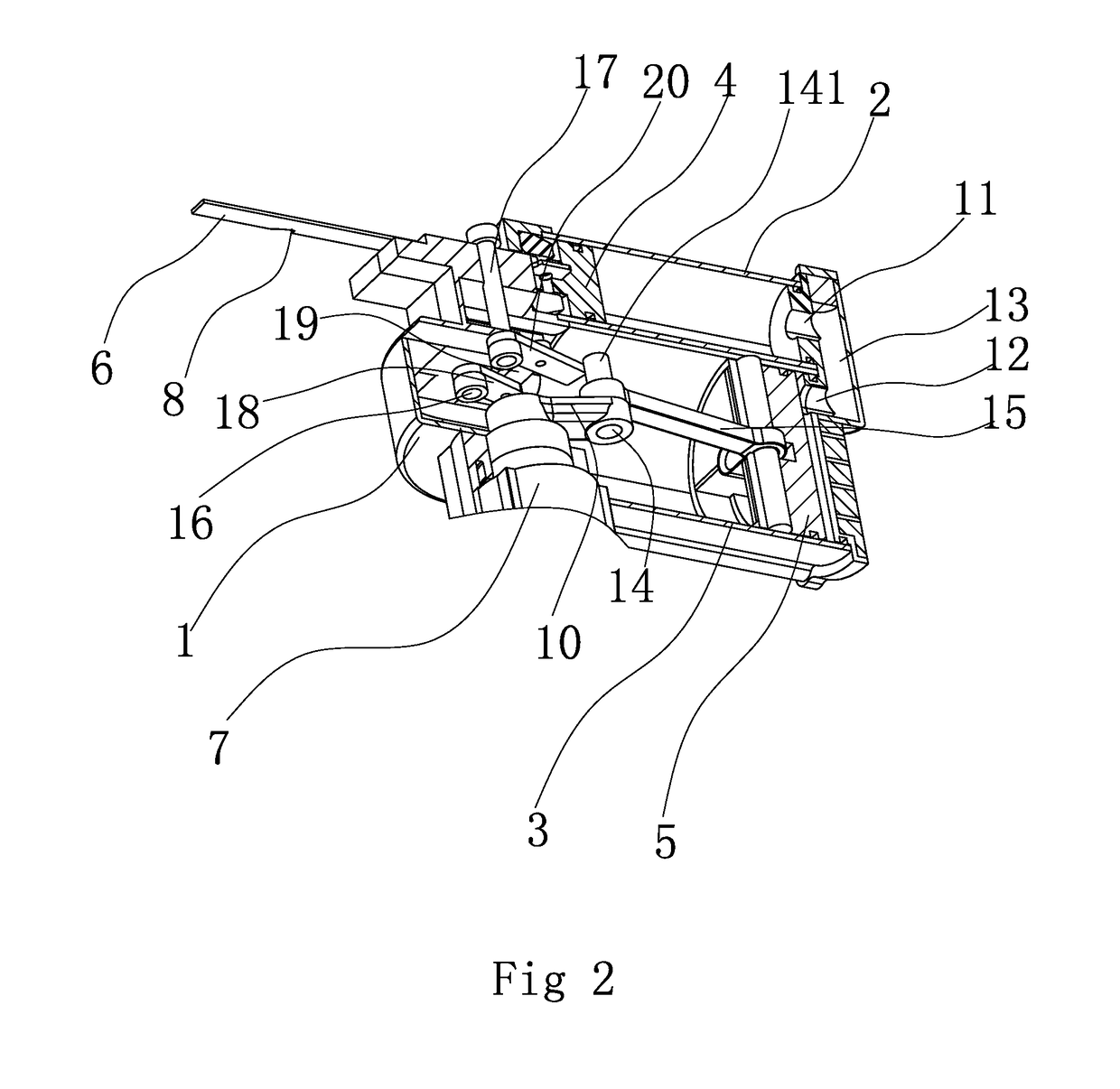
[0027]As shown in FIGS. 1 to 7, one embodiment of the nailing machine includes a housing 1, the first cylinder 2, and the second cylinder 3, whose tail ends communicate with each other. The first cylinder 2 and the second cylinder 3 are arranged side by side on the housing 1. The tail end of the first cylinder 2 is provided with a first hole 11. The tail end of the second cylinder 3 is provided with a second hole 12. The first hole 11 communicates with the second hole 12 through the third hole 13. The first cylinder 2 has a first piston 4 inside. The first piston 4 is fixedly connected to the striker 6. The second cylinder 3 has a second piston 5 inside. And the second piston 5 is connected with the motor 7. The striker 6 has a lock...


PUM


Abstract

The nailing machine includes a closed first cylinder and a closed second cylinder, a working chamber of the first cylinder and a working chamber of the second cylinder are communicated with each other. A first piston inside a first cylinder is fixedly connected with a striker that has a locking part. The locking part could be locked by a pawl. The second cylinder is provided with a second piston reciprocated by a motor between a first position and a second position. When the second piston is in the first position, after the first piston moves inward, the pawl snaps at the locking part of the striker. When the second piston is in the second position, the motor drives the pawl to disengage from the locking part. The motor drives the second piston to compress air, and triggers the pawl, achieving the rapid and continuous firing of strip nails.

Description

BACKGROUND OF THE INVENTIONField of Invention[0001]The present invention pertains to the technical field of machine manufacturing, and more particularly to a nailing device, specifically, a nailing machine.Related Art[0002]A nailing machine that is a nail gun, includes electric nail gun, pneumatic nail gun, gas nail gun, manual nail gun, and so on. A pneumatic nail gun is also known as pneumatic nailing machine. The existing pneumatic nailing machines mostly use the pneumatic pump, generating the air pressure to push the striker, as the power source. High pressure gas drives the striker in the cylinder of the nailing machine to execute the hammering motion, driving nails from the strip nails into the object, or shooting the nails out. Normally, the nail gun body assembly is composed of a gun body, a cylinder, a balancing valve, a trigger assembly, a striker assembly, a cushion, a gun muzzle, and a gun groove. It applies the pressure difference between compressed air and atmospheric,...

Claims


Application Information

Patent Timeline
IPC IPC(8): B25C1/04B25C1/06
CPCB25C1/047B25C1/06
Inventor ZHANG, HUADING
Owner ZHANG HUADING
Why Eureka
Try Eureka