
Apparatus and method for determining feedscrew and barrel wear

a technology of a feed screw and a barrel, applied in the direction of mechanical measuring arrangements, instruments, mechanical means, etc., can solve the problems of widening the gap between the outer edge of the flight and the inner surface of the barrel, high abrasiveness, and poor consistency of plastic materials, so as to achieve efficient and timely

Inactive Publication Date: 2018-08-09
GLYCON CORP
View PDF5 Cites 9 Cited by
  • Summary
  • Abstract
  • Description
  • Claims
  • Application Information

AI Technical Summary

Benefits of technology

The patent describes a new and helpful way to monitor and record the wear and tear of a production installation that uses a barrel and feedscrew combination. This method is efficient and can be done in a timely manner.

Problems solved by technology

Many plastic materials are highly abrasive and tend to wear the flights on the screw thereby widening the gap between the outer edge of the flights and the inner surface of the barrel.
Such a condition will tend to prevent the uniform free flow of material through the barrel thereby causing problems in the consistency of the plastic material.
Other problems that can occur are galling in the barrel through adhesive wear, metal to metal contact within the barrel, and misalignment of the screw through excessive shear or deflection of the screw mechanism.
Such a procedure tended to result in lost production time and did not completely eliminate the occasional breakdowns between regular measurements.
However, one problem encountered when attempting to measure the distances within the barrel using the aforementioned probe relates to the heat generated by the rotation of the screw within the barrel.
The heat generated by use of the screw can potentially damage the sensor of the probe if the sensor is exposed to elevated temperatures within the barrel for an extended period of time.
The measurement of the axial length of the plug may require the use of additional measuring devices and fixtures following the removal of the plug from the barrel, thereby further complicating the process of determining the wear experienced by the barrel.

Method used


Image

  • Apparatus and method for determining feedscrew and barrel wear
  • Apparatus and method for determining feedscrew and barrel wear
  • Apparatus and method for determining feedscrew and barrel wear

Examples


Embodiment Construction

[0032]The following detailed description and appended drawings describe and illustrate various embodiments of the invention. The description and drawings serve to enable one skilled in the art to make and use the invention, and are not intended to limit the scope of the invention in any manner. In respect of the methods disclosed, the steps presented are exemplary in nature, and thus, the order of the steps is not necessary or critical unless noted otherwise.

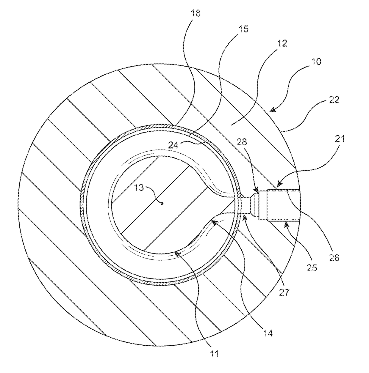
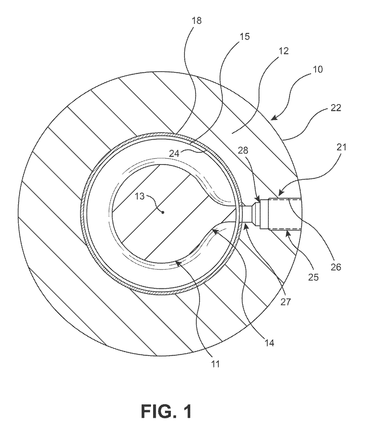
[0033]FIG. 1 illustrates a barrel 10 having a feedscrew 11 disposed therein. The barrel 10 includes a circumferentially extending and cylindrically shaped wall 12 having a central bore 15 formed therein in which the feedscrew 11 is positioned for rotation. The feedscrew 11 extends along a longitudinal axis 13 thereof (extending into the plane of the page) as a cylindrical body with a helical flight 14 formed on an exterior thereof. The wall 12 defining the central bore 15 may be covered by a liner or coating 18 used to reduce we...


PUM

PropertyMeasurementUnit
Distanceaaaaaaaaaa

Abstract

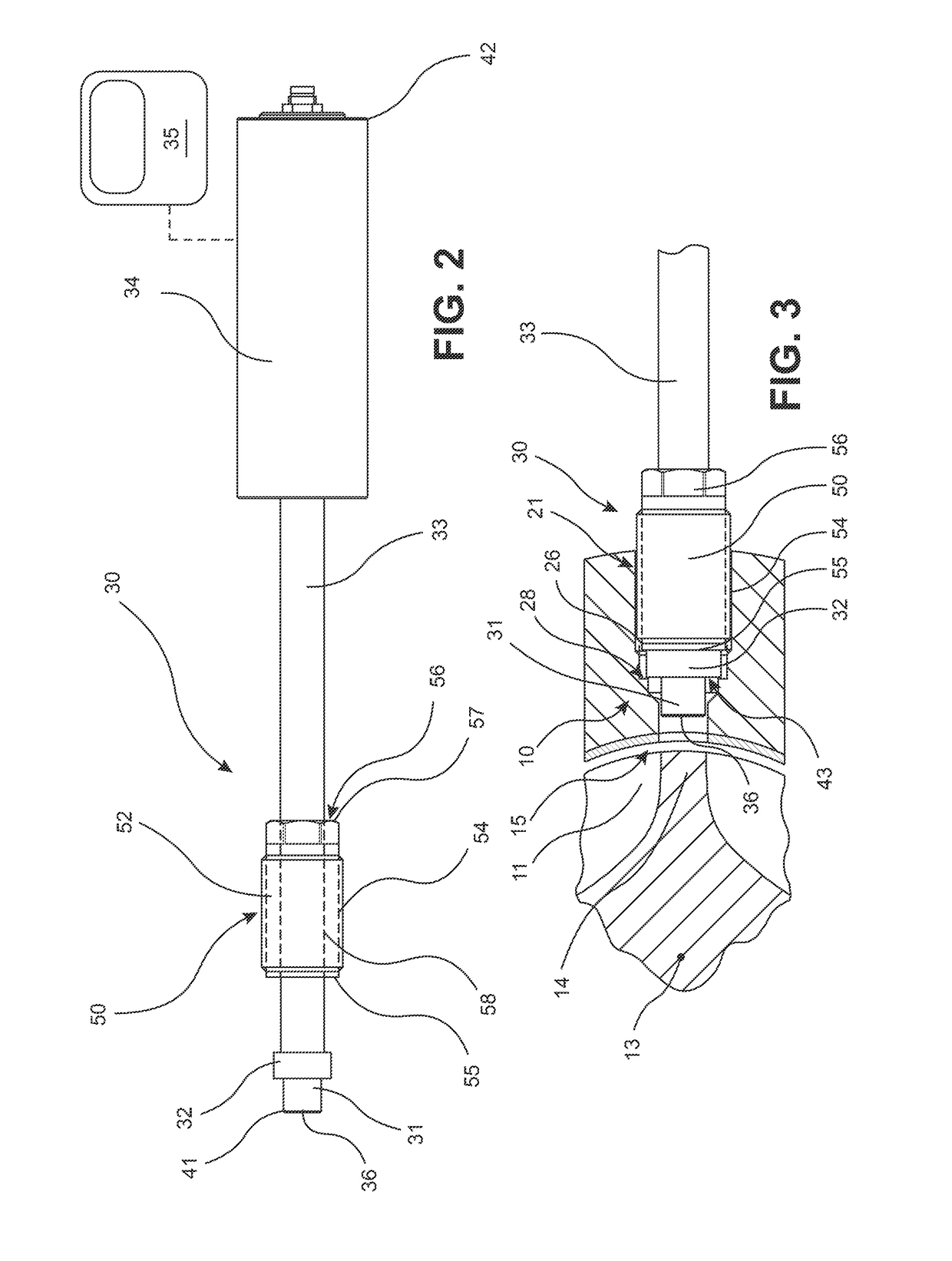
An assembly for measuring wear of a barrel and feedscrew combination, wherein the barrel has a longitudinally extending feedscrew disposed therein and a radially extending measuring aperture formed in a wall thereof, includes a measuring probe having a proximity detecting sensor, a barrel plug for removable insertion into the measuring aperture, and a measuring fixture. The barrel plug is configured to undergo wear in an axial direction thereof while inserted into the measuring aperture. The measuring probe and the barrel plug are installed into the measuring fixture for determining wear of the barrel plug in the axial direction thereof. The measuring probe is further configured for removable insertion into the measuring aperture for measuring wear of a flight of the feedscrew. A spacer and rotational tool cooperate with the measuring probe when installing the measuring probe in the measuring aperture.

Description

FIELD OF THE INVENTION[0001]The invention relates generally to an apparatus and method for detecting wear in a material processing machine and, in particular, to an apparatus and method for determining the wear of a feedscrew flight and the wear of an interior surface of a barrel accommodating the feedscrew.BACKGROUND OF THE INVENTION[0002]Typically, a barrel and feedscrew are used to mix and melt various materials for extrusion, blowmolding, and injection processes. For example, bulk plastic material is fed into an extruder, an injection molding machine, or a blow molder through a barrel or cylinder utilizing a rotating helical screw. Such a machine is operated at an elevated temperature and if it is required to be shut down, the plastic material tends to solidify. Many plastic materials are highly abrasive and tend to wear the flights on the screw thereby widening the gap between the outer edge of the flights and the inner surface of the barrel. Such a condition will tend to preve...

Claims


Application Information

Patent Timeline
IPC IPC(8): G01B5/20B29C47/92B29C48/92
CPCG01B5/204B29C2947/924B29C2947/92123B29C47/92B29B7/728B29C48/92B29C2948/92123B29C2948/924G01N3/56
Inventor KUHMAN, JEFFREY A.HARRIS, RICHARD T.
Owner GLYCON CORP
Learn More