Touch panel device and image display device including the touch panel device

Active Publication Date: 2018-08-09
TRIVALE TECH
View PDF2 Cites 8 Cited by
  • Summary
  • Abstract
  • Description
  • Claims
  • Application Information

AI Technical Summary

Benefits of technology

[0012]The present invention has been made in order to solve the problems as described above, and has an object to provide a touch panel device having high sensitivity that is adaptable to a glove operation and the like even when a protective plate is provided and suitable for use under a high temperature and high humidity condition, and an image display device includin

Problems solved by technology

Such change in relative permittivity is a cause of changing electrostatic capacitance measured by touch sensors.
However, as means of suppressing change in electrostatic capacitance coupling, a protective glass having a black frame printing that is formed of conduc

Method used


Image

  • Touch panel device and image display device including the touch panel device
  • Touch panel device and image display device including the touch panel device
  • Touch panel device and image display device including the touch panel device

Examples


first preferred embodiment

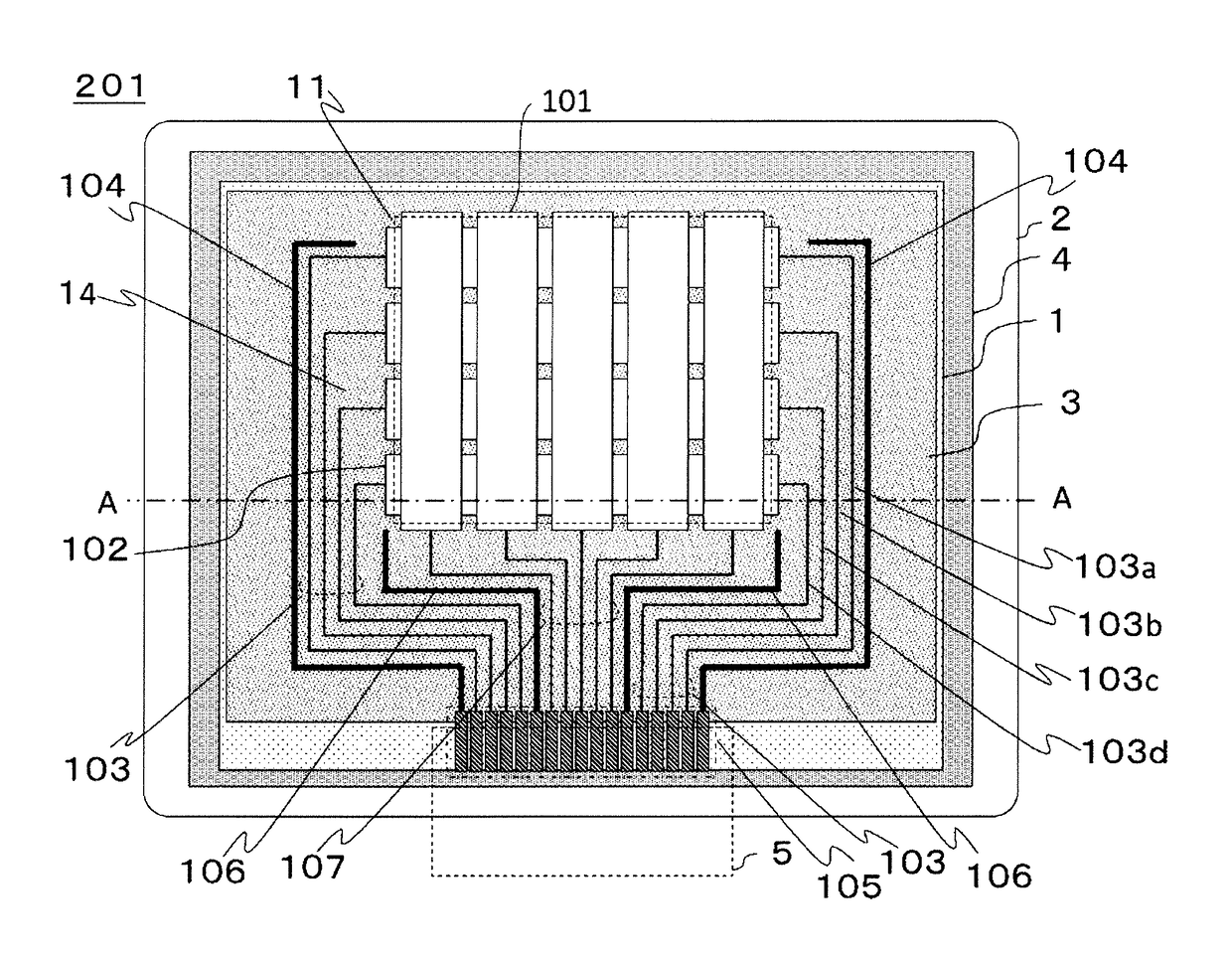
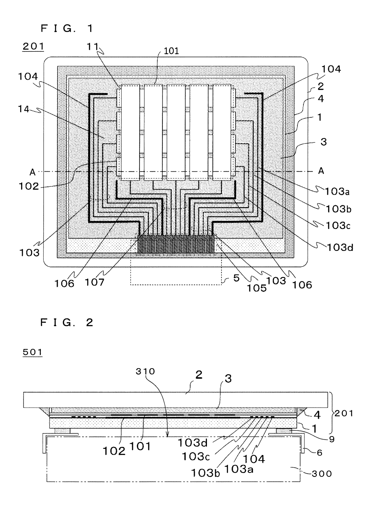
[0027]FIG. 1 is a top view illustrating a structure of a projection-type touch panel device 201 according to this first preferred embodiment. FIG. 2 is a view schematically illustrating a structure of an image display device 501 according to this first preferred embodiment, namely, a cross-sectional view corresponding to a portion indicated by the one dot chain line in the drawing of the touch panel device 201 illustrated in FIG. 1 (portion taken along the line A-A). As in FIG. 1, the projection-type touch panel device 201 includes a touch sensor panel 1, a protective plate 2, a transparent adhesive material 3, a moisture-proof sealing member 4, and a flexible wiring board (flexible printed circuit (FPC)) 5. The touch sensor panel 1 includes a sensor region 11 to be touched by a pointer, and a lead-out wiring region 14 for connecting a plurality of sensors to the FPC 5. The plurality of sensors are connected to an external circuit via the FPC 5. As in FIG. 2, the touch panel device ...

second preferred embodiment

[0058]FIG. 5 is a top view illustrating a structure of a touch panel device 202 according to this second preferred embodiment. FIG. 6 is a view schematically illustrating a structure of an image display device 502 according to this second preferred embodiment, namely, a cross-sectional view corresponding to a portion indicated by the one dot chain line in the drawing of the touch panel device 202 illustrated in FIG. 5 (portion taken along the line B-B). In the touch panel device 202 of this preferred embodiment, unlike the configuration of FIG. 1, a position and a size of the transparent adhesive material 3 are selected so that the sensor region 11 indicated by the dashed line is covered and that the lead-out wiring region 14 is partially uncovered. Thus, in the touch sensor panel 1, a portion right above the sensor region 11 is covered by the transparent adhesive material 3, and a space 12 is provided above a part of the lead-out wiring region 14, which is not covered by the transp...


PUM


Abstract

A touch sensor panel includes a plurality of sensors. A protective plate protects the touch sensor panel. A transparent adhesive material attaches the touch sensor panel and the protective plate. A moisture-proof sealing member has water vapor permeability that is lower than water vapor permeability of the transparent adhesive material. A flexible wiring board connects the plurality of sensors to an external circuit. The transparent adhesive material has a region that is out of contact with the protective plate or the touch sensor panel, and at least a part of the region is covered by the moisture-proof sealing member.

Description

BACKGROUND OF THE INVENTIONField of the Invention[0001]The present invention relates to an electrostatic capacitive touch panel device, and an image display device including the electrostatic capacitive touch panel device.Description of the Background Art[0002]A touch panel device that detects a touch of a pointer such as a finger and determines coordinates indicating a position of the touch (touch coordinates) is widely used in various information processing devices. Particularly, a touch panel device in which a touch panel is mounted on a screen of a display device is widespread as a new user interface of information processing devices.[0003]In a projection-type electrostatic capacitive system being one of electrostatic capacitive systems, a detection circuit detects slight change in touch sensors provided in a touch panel, which is caused by electrostatic capacitance of a human finger. Then, based on such detection results, positional coordinates in the touch panel are calculated...

Claims


Application Information

Patent Timeline
IPC IPC(8): G06F3/044G06F3/041
CPCG06F3/044G06F3/0412G06F3/0416G06F2203/04107G06F3/0446G06F3/0445G06F3/04164
Inventor MORI, SEIICHIRO
Owner TRIVALE TECH
Why Eureka
Try Eureka