Secondary battery and secondary battery manufacturing method

a secondary battery and manufacturing method technology, applied in the direction of cell components, final product manufacturing, sustainable manufacturing/processing, etc., can solve the problems of difficult to bring the ends of the collector foil and the extension parts of the collector terminal into contact with each other, the collector foil end can be installed on the electrode body easily and easily and stably joined to the electrode body. , the effect of easy installation

Active Publication Date: 2018-08-09
TOYOTA JIDOSHA KK
View PDF3 Cites 3 Cited by
  • Summary
  • Abstract
  • Description
  • Claims
  • Application Information

AI Technical Summary

Benefits of technology

[0032]According to the present disclosure, a secondary battery having a configuration that allows a collector terminal to be installed on an electrode body easily and joined to the electrode body easily and stably, and a manufacturing method of this secondary battery can be provided.

Problems solved by technology

If the slit width is too small when inserting the ends of the plurality of collector foils in a bundled state into the slit, it is difficult to insert the ends of the collector foils into the slit.
As a result, it may be difficult to install the collector terminal on the electrode body.
On the other hand, if the slit width is too large, i.e., the interval between two extension portions is too large when joining the ends of the plurality of collector foils in a bundled state to the collector terminal by laser welding, it is difficult to bring the ends of the collector foils and the extension parts of the collector terminal into contact with each other, and a welding laser passes through the slit and reaches the collector foils or separators located on the inner side of the collector terminal (so-called laser pass-through).
As a result, it may be difficult to perform welding appropriately.

Method used


Image

  • Secondary battery and secondary battery manufacturing method
  • Secondary battery and secondary battery manufacturing method
  • Secondary battery and secondary battery manufacturing method

Examples


embodiment 1

[0055]Secondary Battery 100

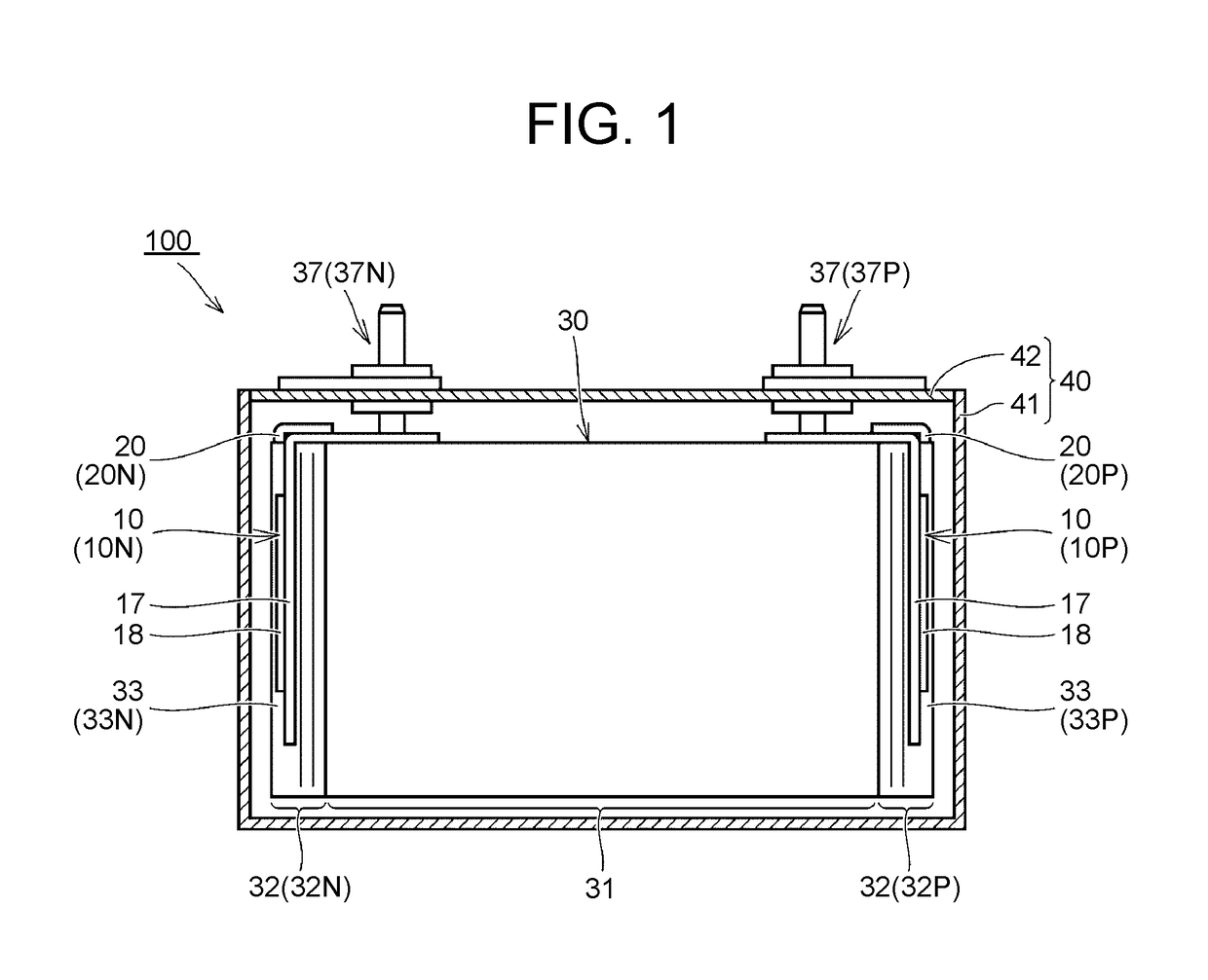
[0056]FIG. 1 is a sectional view showing a secondary battery 100 in Embodiment 1. The secondary battery 100 is a non-aqueous electrolyte secondary battery, and for example, can be used as a lithium ion battery. The secondary battery 100 is used to drive a vehicle, for example, and is installed in a hybrid electric vehicle that is powered by an internal combustion engine, such as a gasoline engine or a diesel engine, and by a motor that is supplied with electricity from a chargeable-dischargeable battery, a plug-in hybrid electric vehicle that can be charged from outside, an electric vehicle, etc.

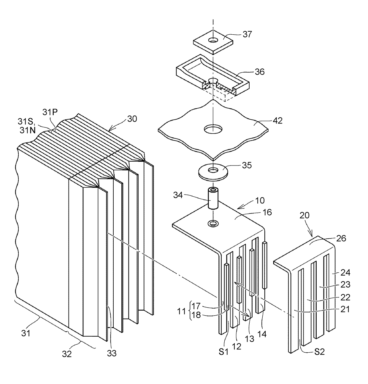
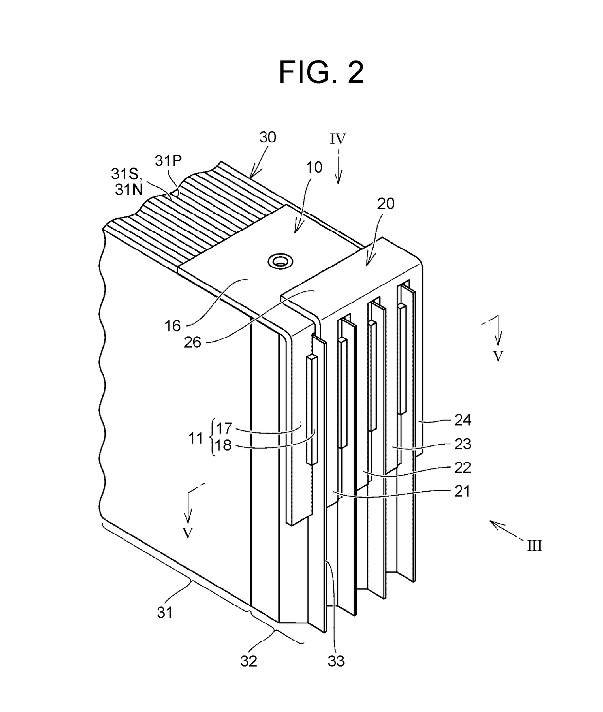
[0057]The secondary battery 100 includes an electrode body 30, a case body 40, a positive-electrode external terminal 37P, a negative-electrode external terminal 37N, positive-electrode collector terminals 10P, 20P, and negative-electrode collector terminals 10N, 20N. Hereinafter, when no distinction is made between the positive-electrode external terminal 37P and ...

example

[0114]Unlike in Comparative Examples 1 and 2, in Example, the part functioning as the collector terminal is composed of two separate members, the first collector terminal 10 and the second collector terminal 20. Thus, the good results, 10 / 10 in both Evaluations 1 and 2, were attained. Therefore, it can be said that the configuration based on Embodiment 1 can provide a secondary battery having a configuration that allows a collector terminal to be easily installed on an electrode body and easily joined to the electrode body, and a manufacturing method of this secondary battery.

embodiment 2

[0115]A secondary battery manufacturing method in Embodiment 2 will be described with reference to FIG. 16. In the arrangement step (FIG. 8 to FIG. 10) in Embodiment 1, the second collector terminal 20 is laid on the outer side of the first collector terminal 10, and then the collector foil connection portions 33 are passed into the slits formed between the first collector terminal 10 and the second collector terminal 20.

[0116]As shown in FIG. 16, in the arrangement step, the second collector terminal 20 may be laid on the first collector terminal 10 after the collector foil connection portions 33 are inserted into the slits S1 of the first collector terminal 10. This configuration can produce effects and advantages similar to those of Embodiment 1.


PUM

PropertyMeasurementUnit
weld lengthaaaaaaaaaa
thicknessaaaaaaaaaa
thicknessaaaaaaaaaa

Abstract

A secondary battery includes: an electrode body including an electrode main body, a collector foil protrusion section, and a collector foil connection portion; a first collector terminal including a first extension part that is welded to the collector foil connection portion; and a second collector terminal that is a member separate from the first collector terminal and includes a second extension part welded to the collector foil connection portion. The first extension part and the second extension part are located on the opposite sides of the collector foil connection portion. The secondary battery includes a welded joint at which both the first extension part and the second extension part are welded to the collector foil connection portion such that the first extension part, the second extension part, and the collector foil connection portion are united. The first collector terminal and the second collector terminal are united through the welded joint.

Description

INCORPORATION BY REFERENCE[0001]The disclosures of Japanese Patent Application No. 2017-048305 filed on Mar. 14, 2017 and Japanese Patent Application No. 2017-19425 filed on Feb. 6, 2017 including the specifications, drawings and abstracts are incorporated herein by reference in its entirety.BACKGROUND1. Technical Field[0002]The present disclosure relates to a secondary battery and a secondary battery manufacturing method.2. Description of Related Art[0003]To realize high-efficiency discharge and high capacity, an electrode body of a secondary battery is formed by laminating or rolling a plurality of electrode foils. The electrode body is housed inside a case body along with a collector terminal (also called a current collector), and an external terminal is arranged on an outer side of the case body (on a lid). The collector terminal mounted on the electrode body electrically connects the electrode body and the external terminal to each other.[0004]As disclosed in Japanese Patent Ap...

Claims


Application Information

Patent Timeline
Patent Type & Authority Applications(United States)
IPC IPC(8): H01M4/66H01M2/06H01M2/26B23K11/00H01M2/04H01M2/30H01M50/15H01M50/176H01M50/528H01M50/531H01M50/54H01M50/543H01M50/55H01M50/553
CPCH01M4/661H01M2/06H01M2/26B23K11/0026H01M2/0469H01M2/30H01M10/0525H01M10/0404H01M50/176H01M50/553H01M50/15H01M50/54H01M50/55B23K26/0869B23K26/32B23K26/242B23K2101/18B23K2101/36B23K2103/10B23K2103/12Y02E60/10H01M50/528Y02P70/50
Inventor YAMAMOTO, SATOMIMATSUMOTO, MIZUHOTAKAMATSU, HIROSHIIMANISHI, HIROAKIMURATA, ICHIROKOZUKI, KIYOMI
Owner TOYOTA JIDOSHA KK
Why Eureka
Try Eureka