
Temporary bypass balloon catheter

a balloon catheter and temporary technology, applied in balloon catheters, medical science, surgery, etc., can solve the problems that the endovascular treatment of aneurysms with preservation of the parent artery is difficult to implement, and achieve the effect of improving the success rate of endovascular treatment, simple technique, and facilitating temporary bypass

Active Publication Date: 2018-08-16
WALZMAN DANIEL EZRA
View PDF0 Cites 11 Cited by
  • Summary
  • Abstract
  • Description
  • Claims
  • Application Information

AI Technical Summary

Benefits of technology

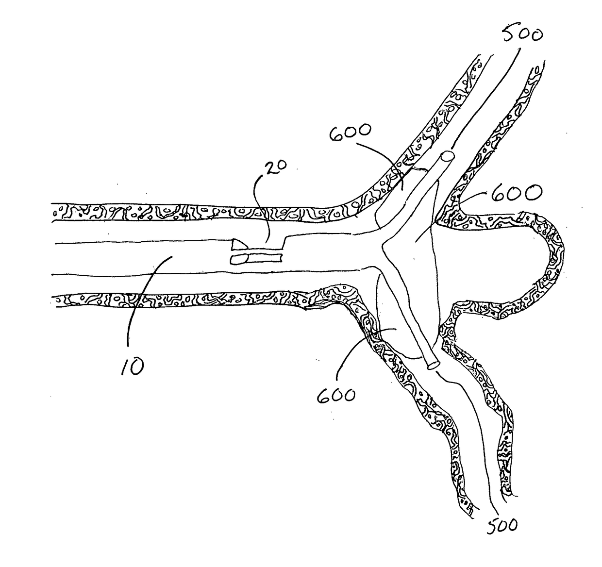
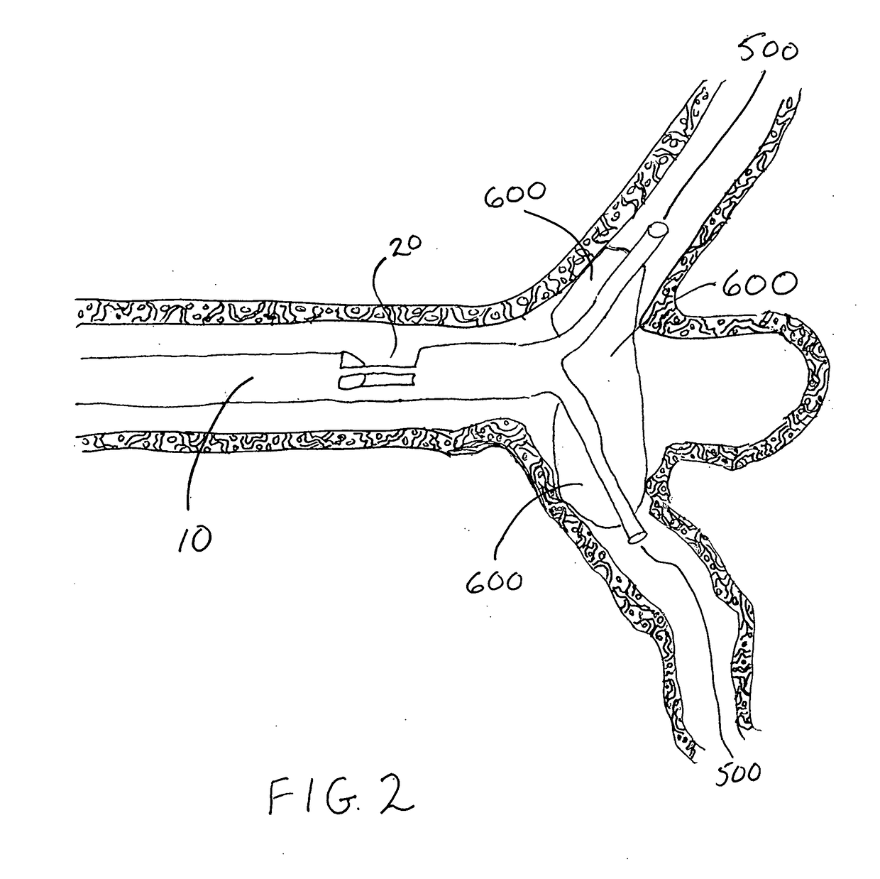
The present invention is a device and technique to improve the success rates of endovascular treatments of aneurysms with preservation of the parent artery while minimizing risks of treatment. It provides a balloon delivery catheter with a bypass element to allow continued perfusion of the involved vascular territory while simultaneously inflating the balloon across the neck of an aneurysm to facilitate treatment. The device also has at least one proximal inflow "window" that can allow delivery of micro-catheters and / or other therapeutic devices to facilitate treatment of such aneurysms. The invention is composed of a catheter with at least one distal end hole, at least one bypass window proximal to the end hole, and a balloon element between the end hole and the bypass window. The balloon element can be inflated to help facilitate the aneurysmal therapy. The invention can taper before the bypass windows to allow more flow into the windows and can branch after the proximal bypass "window(s)".

Problems solved by technology

Endovascular treatment of aneurysms with preservation of the parent artery continues to be difficult to implement.

Method used


Image

  • Temporary bypass balloon catheter
  • Temporary bypass balloon catheter
  • Temporary bypass balloon catheter

Examples


Embodiment Construction

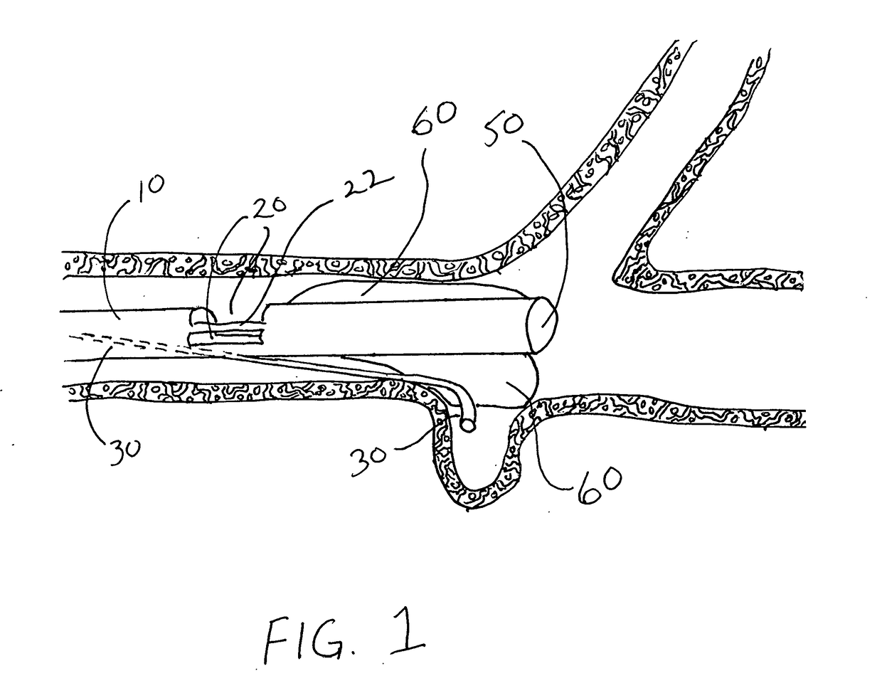
[0028]The present invention is composed of a catheter 10 with a distal end hole 50, at least one bypass window 20 proximal to said end hole 50 and a balloon 60 element between said end hole 50 and said bypass window 20. The present invention is capable of deploying said balloon 60 element across the neck of a target aneurysm (shown depending in cutaway profile) while simultaneously positioning said bypass windows 20 proximally of said target aneurysm so as to allow a micro-catheter 30 to be pushed from the proximal end of said catheter 10, through said bypass window 20, around said balloon 60 and into said target aneurysm. Said micro-catheter 30, once deployed, is capable of delivering material into said target aneurysm.

[0029]Referring now to FIG. 1, the preferred embodiment is composed of a balloon 60 mounted to a catheter 10 similar to a Merci / Concentric / Stryker Flowgate Balloon Guide Catheter. The present invention differs from the Merci / Concentric / Stryker Flowgate Balloon Guide ...


PUM


Abstract

A balloon catheter for treating aneurysms or other intraluminal target sites, having at least one bypass window through which blood flows temporarily and out at least one end hole, and a balloon mounted near the end hole, such that there is no need for repeated inflation / -deflation cycles. The invention has an elongated tube, a balloon disposed between the most distal said window and said end hole, and at least two channels. A first channel passes from the proximal end of said tube to the bypass window to allow blood to flow into said window and out said end hole, and a second channel passing from the proximal end of said tube to said balloon to allow inflation material to enter said balloon.In optional embodiments, a micro-catheter may pass through to treat a target site; the inner tube and balloon may be branched to facilitate treatment at a vascular branch, such as for a wide-neck aneurysm by balloon tamponade, a micro-catheter extension or other device passing through a bifurcation hole at the branch point.

Description

BACKGROUND OF THE INVENTIONField of the Invention[0001]This invention relates in general to medical equipment and procedures. In particular, the invention relates to balloon catheters for use in performing certain endovascular procedures. More particularly, the present invention pertains to balloon catheters with a bypass element.Background Art[0002]Temporary balloon occlusion has become a routine and medically accepted technique for the management of patients with aneurysms or intracranial or head / neck tumors. The use of temporary balloon occlusion is particularly useful for the management of patients with aneurysms or intracranial or head / neck tumors who will likely require prolonged intra-operative or permanent occlusion of the internal carotid artery (ICA).[0003]Endovascular procedures are generally less invasive procedure than alternative procedures and are used to treat problems affecting the blood vessels, such as an aneurysm, which is a swelling or “ballooning” of the blood ...

Claims


Application Information

Patent Timeline
IPC IPC(8): A61M25/10A61M25/00A61B17/12
CPCA61M25/1025A61M25/0071A61M25/0029A61M25/0084A61B17/12136A61B17/1204A61B17/12109A61M2025/0042A61M2025/1052A61M2025/1061A61M2025/1097A61B17/12195A61M2025/0089A61B2017/1205A61B17/12031A61B17/12113A61M2025/1095A61B17/12036A61B17/12045A61B17/12186
Inventor WALZMAN, DANIEL E.
Owner WALZMAN DANIEL EZRA
Learn More