Ophthalmic lens customization system and method

a technology of ophthalmology and customization system, which is applied in the field of customizing ophthalmology lenses, can solve the problems of prior art field customization of lenses, and achieve the effect of precise physical orientation

Active Publication Date: 2018-08-16
PERFECT IP
View PDF0 Cites 3 Cited by
  • Summary
  • Abstract
  • Description
  • Claims
  • Application Information

AI Technical Summary

Benefits of technology

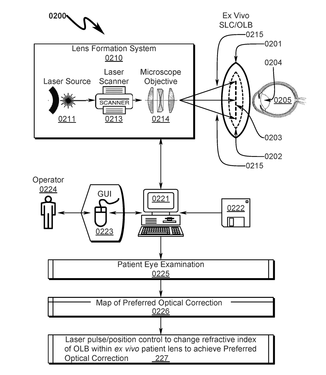
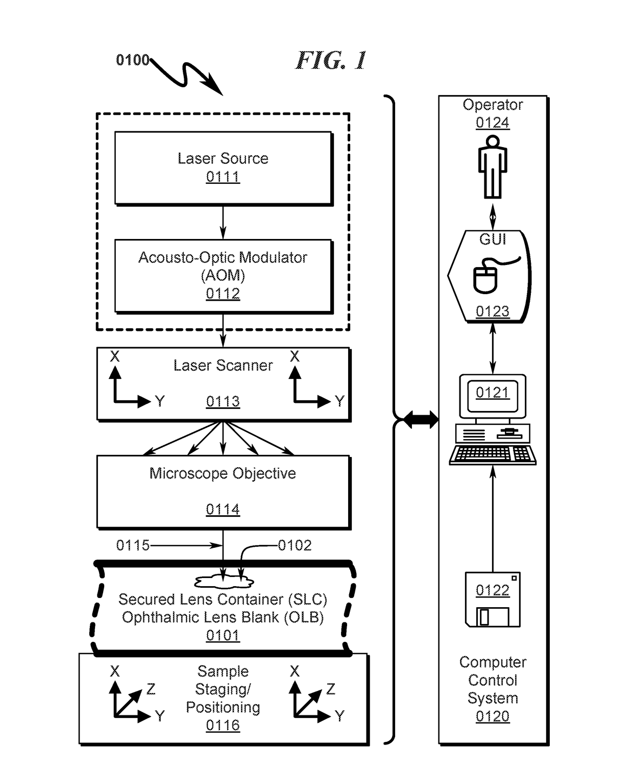
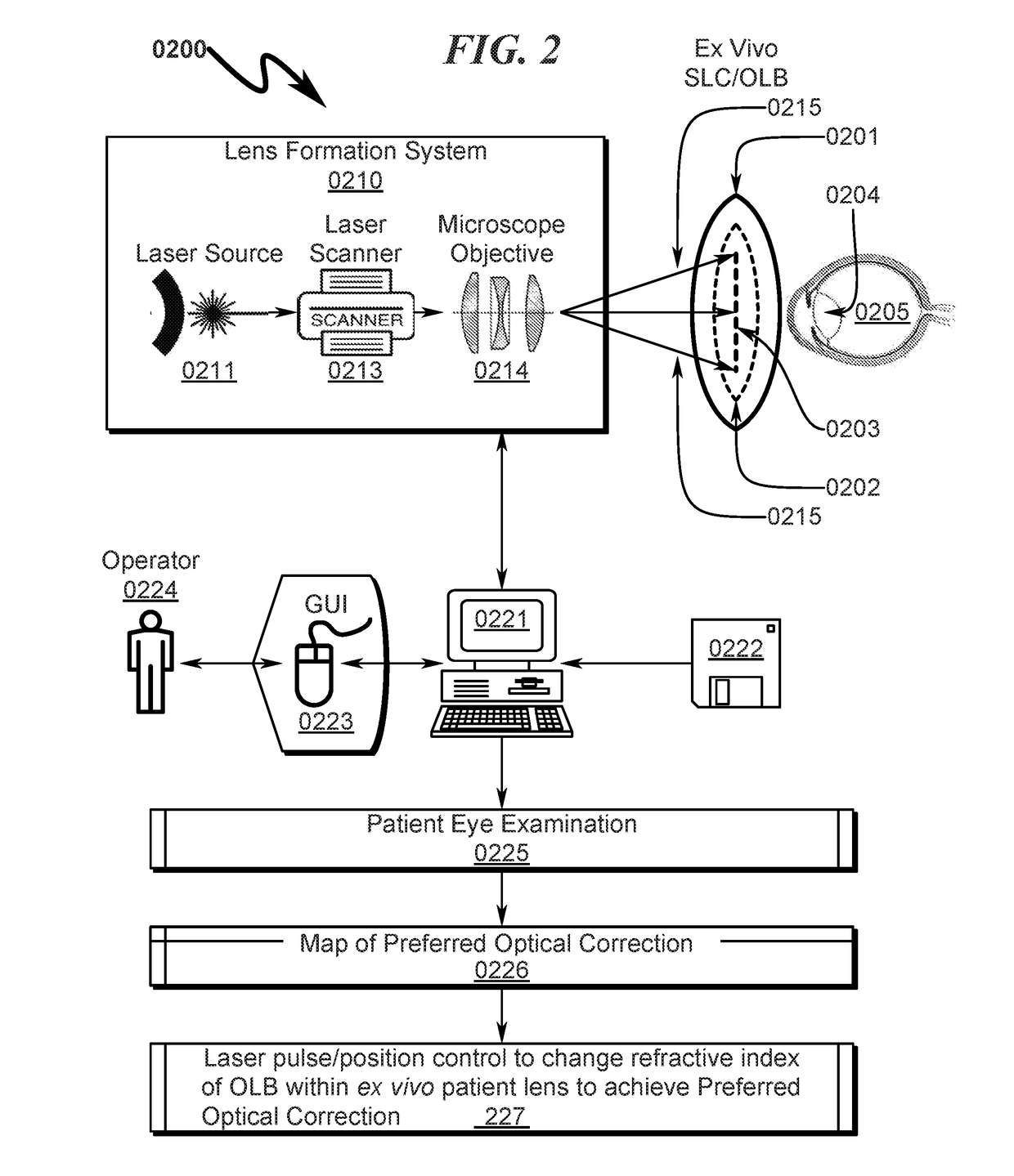
[0021]The OLB is typically composed of a clear material (acrylic; silicon; poly(methyl methacrylate)(PMMA); PMMA plastic, etc,) that has been infused with an ultraviolet (UV) absorbing compound rendering it amenable to customized spatial modification (CSM) of its refractive index via the use of pulsed laser radiation (PLR). The focus spot of the pulsed laser beam is moved inside the lens material to create a pattern of changes in the material, creating a three dimensional lens. Different patterns will adjust different lens properties, for example, asphericity of the lens, cylindrical diopter, spherical diopter or addition of multifocality. Multiple patterns or integration of different patterns may be used to create more than one change to the refractive index, for example, asphericity, multifocality and/or diopter change may be adjusted in single treatment of the lens. The CSM of refractive index eliminates the need for remote laboratory fabrication of a customized intraocular lens (IOL) for the patient.
[0022]The

Problems solved by technology

There is no provision in the prior art for field customization of le

Method used


Image

  • Ophthalmic lens customization system and method
  • Ophthalmic lens customization system and method
  • Ophthalmic lens customization system and method

Examples


##c embodiment

Exemplary SLC Embodiment Overview (1000)-(1600)

[0207]An overview of the SLC and corresponding OLB structures typically utilized with the present invention are detailed in FIG. 10 (1000)-FIG. 16 (1600).

[0208]An exemplary square SLC embodiment is generally depicted in FIG. 10 (1000)-FIG. 16 (1600). As depicted in FIG. 10 (1000) it can be seen that a baseplate fixture (1001, 1101) securely retains the square SLC (1002, 1102) to permit laser radiation to be focused on the OLB contained within the SLC (1002, 1102). The assembly view in FIG. 12 (1200) details the SLC (1210), OLB (1220), hermetic seal (1230), and laser access window (1240). FIG. 13 (1300)-FIG. 15 (1500) depict the SLC in various stages of disassembly. It should be noted in this particular embodiment the hermetic seal (1230) extends around the edges of the SLC holder and allows the lens cavity to be filled with fluid through the laser access window (1240) which is installed after fluid filling of the lens cavity. The laser ...

##c embodiment (

Exemplary Rectangular Cartridge SLC Embodiment (4100)-(6400)

[0213]An exemplary rectangular cartridge SLC embodiment is generally depicted in FIG. 41 (4100)-FIG. 64 (6400). As depicted in FIG. 41 (4100) it can be seen that a baseplate fixture (4101) securely retains the rectangular cartridge SLC (4102) to permit laser radiation to be focused on the OLB contained within the SLC (4102). Further detail of the interaction between the baseplate fixture (4101) and the square SLC (4102) can be seen by inspection of FIG. 41 (4100)-FIG. 48 (4800). Detail views of the SLC with OLB installed are depicted in FIG. 49 (4900)-FIG. 56 (5600). The cavity in which the OLB is retained within the SLC is generally filled with a fluid suitable for transmission of laser radiation to the OLB during the customization process. This fluid may include but is not limited to distilled water and / or deionized water and / or a physiological saline solution.

[0214]Additional detail of the exemplary SLC and OLB can be se...


PUM

PropertyMeasurementUnit
Timeaaaaaaaaaa
Timeaaaaaaaaaa
Sizeaaaaaaaaaa

Abstract

A system/method allowing personalized ex vivo customization of a generic ophthalmic lens blank (OLB) or ophthalmic lens with known diopter (OKD) based on localized field-measured patient characteristics is disclosed. The OLB is composed of a clear material that contains an ultraviolet (UV) absorbing compound. The refractive index of a portion of the clear material may be customized by spatial modification (CSM) of its refractive index via the use of pulsed laser radiation (PLR). The customization of clear material (i) creates a lens which cannot be created otherwise, or (ii) eliminates the need for remote laboratory fabrication of a customized intraocular lens (IOL) for the patient. The OLB is retained within a secured lens container (SLC) providing for precise physical orientation of the OLB haptics and OLB lens structure with respect to the application of PLR to the OLB. The SLC contains a lens filler material (LFM) covering the OLB and is hermetically sealed after the OLB has been positioned within the SLC interior and prior to sterilization of the SLC+OLB combination.

Description

CROSS REFERENCE TO RELATED APPLICATIONS[0001]This application is a continuation-in-part of U.S. patent application Ser. No. 15 / 870,140, filed on Jan. 12, 2018, which claims benefit under 35 U.S.C. § 119 and incorporates by reference United States Provisional Patent Application for OPHTHALMIC LENS CUSTOMIZATION SYSTEM AND METHOD by inventors Steven Edward Smothers and Ruth (nmn) Sahler, filed with the USPTO on Feb. 16, 2017, with serial number 62 / 460,043, confirmation number 1036, docket APEIP.0109P. This application further includes by reference U.S. Pat. No. 9,023,257 issued on May 5, 2015 for HYDROPHILICITY ALTERATION SYSTEM AND METHOD by inventors Ruth (nmn) Sahler, Stephen Q. Zhou, and Josef F. Bille.PARTIAL WAIVER OF COPYRIGHT[0002]All of the material in this patent application is subject to copyright protection under the copyright laws of the United States and of other countries. As of the first effective filing date of the present application, this material is protected as un...

Claims


Application Information

Patent Timeline
IPC IPC(8): B29D11/00G02C7/10
CPCB29D11/00461G02C7/10B29K2105/24B29K2105/256B29D11/023A61F2/16G02C7/022A61F2240/002
Inventor SMATHERS, STEVEN EDWARDSAHLER, RUTH
Owner PERFECT IP
Why Eureka
Try Eureka