Electronic brake system and control method thereof

Active Publication Date: 2018-08-16
HL MANDO CORP
View PDF2 Cites 7 Cited by
  • Summary
  • Abstract
  • Description
  • Claims
  • Application Information

AI Technical Summary

Benefits of technology

[0021]The hydraulic pressure of the wheel cylinder may be increas

Problems solved by technology

However, an on/off type valve has a problem in that when characteristics are implemented as an

Method used


Image

  • Electronic brake system and control method thereof
  • Electronic brake system and control method thereof
  • Electronic brake system and control method thereof

Examples


Embodiment Construction

[0028]Hereinafter, embodiments of the present disclosure will be described in detail with reference to the accompanying drawings. The following embodiments are provided to fully convey the spirit of the present disclosure to those skilled in the art. The present disclosure is not limited to the embodiments described herein but may be embodied in other forms. In the drawings, illustration of portions not related to description may be omitted in order to clarify the present disclosure, and sizes of components may be slightly exaggerated to help understanding of the present disclosure.

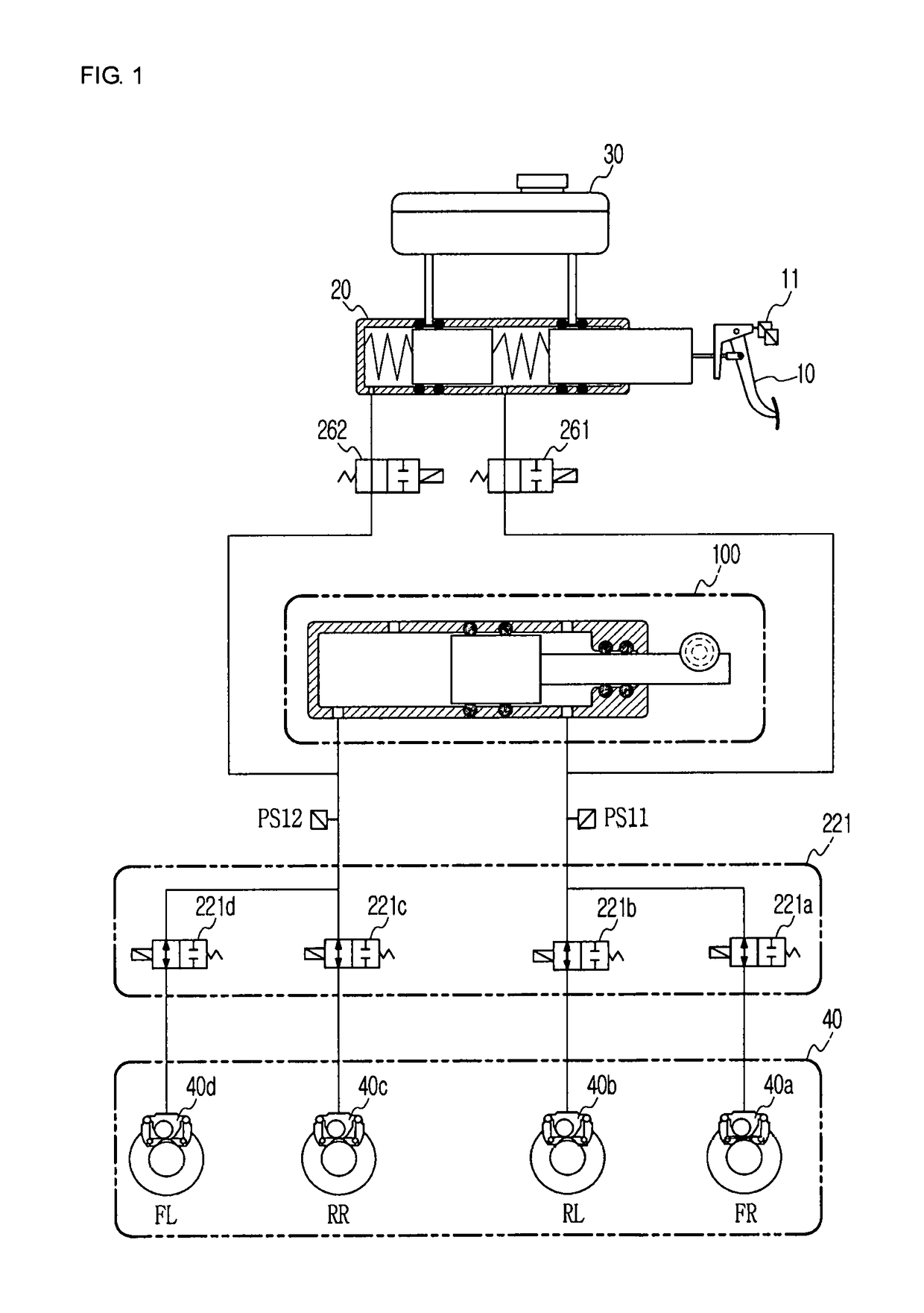
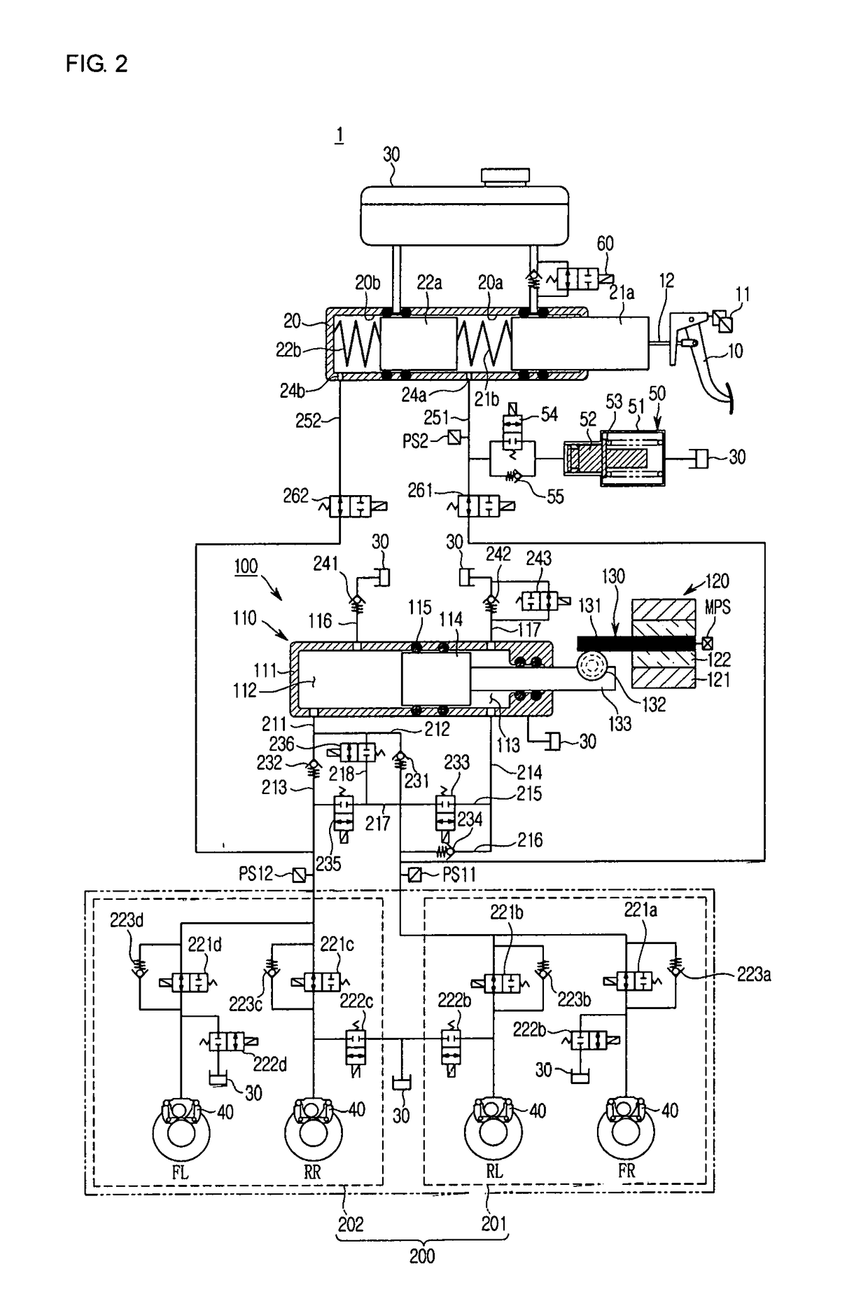
[0029]FIG. 1 is a schematic hydraulic circuit diagram of an electronic brake system according to an embodiment of the present disclosure, and FIG. 2 is a hydraulic circuit diagram showing a state of the electronic brake system according to the embodiment of the present disclosure during non-braking.

[0030]Referring to FIG. 1, conventionally, an electronic brake system 1 includes a reservoir 30 for storing ...


PUM


Abstract

Disclosed herein is an electronic brake system. An electronic brake system according to an embodiment of the present disclosure, which is an electronic brake system including a pedal displacement sensor configured to sense displacement of a brake pedal according to a pedal effort of the brake pedal, a hydraulic pressure supply device configured to generate a hydraulic pressure using a rotational force of a motor operated by an electrical signal output from the pedal displacement sensor, and a hydraulic control unit configured to transmit a hydraulic pressure discharged from the hydraulic pressure supply device to wheel cylinders provided on respective wheels, includes a plurality of valves configured to adjust the hydraulic pressures transmitted to the wheel cylinders, a pressure measurer configured to measure hydraulic pressures of the wheel cylinders and a hydraulic pressure of the hydraulic control unit, and a controller configured to control an electromagnetic force of the valve when a difference between the measured hydraulic pressure of the wheel cylinder and the measured hydraulic pressure of the hydraulic control unit is more than a preset first threshold value during an anti-lock braking system (ABS) operation.

Description

CROSS-REFERENCE TO RELATED APPLICATION[0001]This application claims the benefit of Korean Patent Application No. 2017-0021047, filed on Feb. 16, 2017 in the Korean Intellectual Property Office, the disclosure of which is incorporated herein by reference.BACKGROUND1. Field[0002]Embodiments of the present disclosure relate to an electronic brake system, and more particularly, to an electronic brake system for reducing operating noise and vibration during an anti-lock braking system (ABS) operation, and a control method thereof.2. Description of the Related Art[0003]A vehicle is essentially equipped with a brake system for braking. Recently, various types of systems for obtaining a more powerful and stable braking force are being proposed.[0004]Examples of the brake system include an anti-lock braking system (ABS) which prevents slippage of wheels during braking, a brake traction control system (BTCS) which prevents slippage of driving wheels during sudden unintended acceleration or ra...

Claims


Application Information

Patent Timeline
IPC IPC(8): B60T13/68B60T13/74
CPCB60T13/686B60T13/745B60T2270/10B60T2270/82B60T2270/88B60T8/4081B60T8/17B60Y2306/09B60T8/00
Inventor SON, JOO-HEE
Owner HL MANDO CORP
Why Eureka
Try Eureka