Propulsor assembly for an aircraft

Active Publication Date: 2018-08-16
GENERAL ELECTRIC CO
View PDF0 Cites 16 Cited by
  • Summary
  • Abstract
  • Description
  • Claims
  • Application Information

AI Technical Summary

Benefits of technology

[0006]In one embodiment, an aircraft propulsor assembly includes a fan having a nacelle and plural fan blades radially disposed within the nacelle. The fan blades are configured to be rotated by torque generated by a turbine engine of an aircraft to generate thrust for propelling the aircraft. The assembly also includes an electric motor including a stator in the nacelle of the fan and a rotor in tips of two or more of the fan blades. The electric motor is configured to generate torque that also rotates the fan blades to generate thrust for propelling the aircraft. The assembly also includes a controller configured to reduce or prevent an increase in an operating temperature of the turbine engine of the aircraft by automatically supplanting at least some of the torque generated by the turbine

Problems solved by technology

Fuel costs are a major factor in air travel.
Reducing usage of jet fuel in transporting pa

Method used


Image

  • Propulsor assembly for an aircraft
  • Propulsor assembly for an aircraft
  • Propulsor assembly for an aircraft

Examples


Example

[0013]Reference will now be made in detail to present embodiments of the inventive subject matter, one or more examples of which are illustrated in the accompanying drawings. The detailed description uses numerical and letter designations to refer to features in the drawings. Like or similar designations in the drawings and description have been used to refer to like or similar parts of the inventive subject matter. As used herein, the terms “first”, “second”, and “third” may be used interchangeably to distinguish one component from another and are not intended to signify location or importance of the individual components.

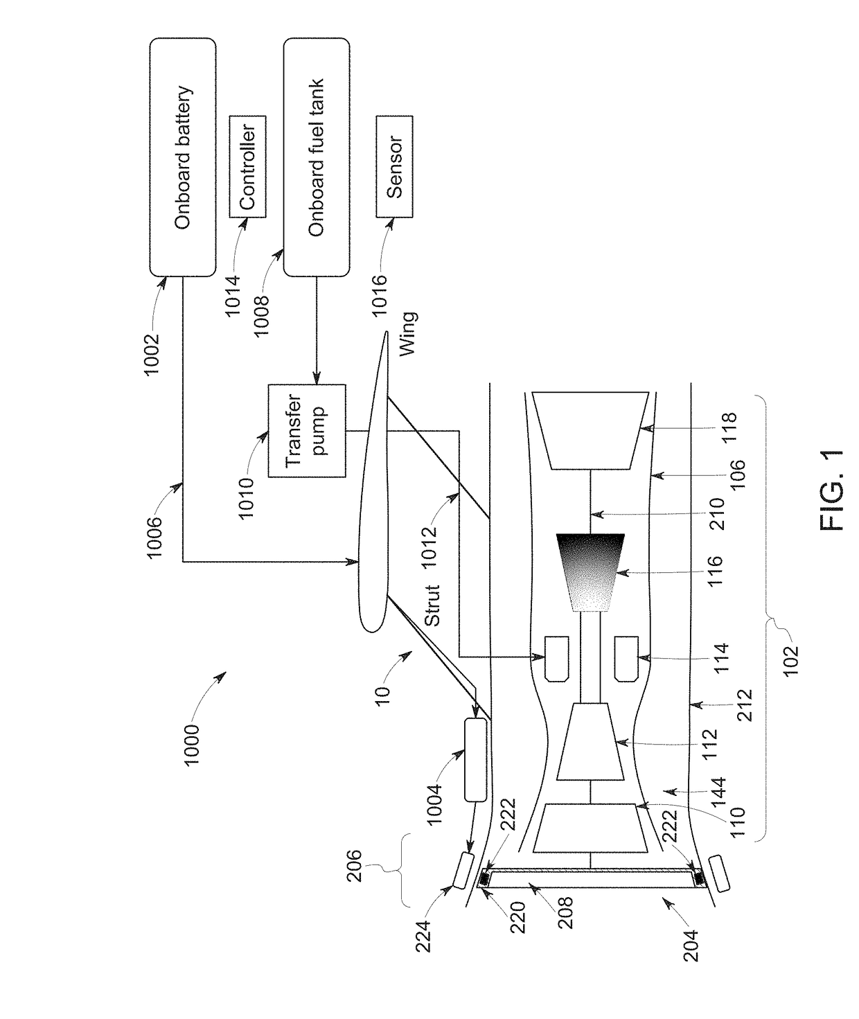
[0014]FIG. 1 is a schematic, cross-sectional view of an auxiliary propulsor assembly 1000 in accordance with another embodiment of the inventive subject matter. The propulsor assembly 1000 can represent one or more of the other propulsor assemblies shown and / or described in the applications that are incorporated by reference into this application, or optionally ca...


PUM


Abstract

An aircraft propulsor assembly includes a fan having a nacelle and plural fan blades radially disposed within the nacelle. The fan blades are configured to be rotated by torque generated by a turbine engine of an aircraft to generate thrust for propelling the aircraft. The assembly also includes an electric motor including a stator in the nacelle of the fan and a rotor in tips of two or more of the fan blades. The electric motor is configured to generate torque that also rotates the fan blades to generate thrust for propelling the aircraft. The assembly also includes a controller configured to reduce or prevent an increase in an operating temperature of the turbine engine of the aircraft by automatically supplanting at least some of the torque generated by the turbine engine with the torque generated by the electric motor.

Description

CROSS-REFERENCE TO RELATED APPLICATIONS[0001]This application claims priority to U.S. Provisional Application No. 62 / 509,402, which was filed on 22 May 2017, and also is a continuation-in-part of U.S. patent application Ser. No. 15 / 430,052, which was filed on 10 Feb. 2017. The entire disclosures of these applications are incorporated herein by reference.FIELD[0002]The present subject matter relates generally to a propulsion system for an aircraft, and an aircraft including the same.BACKGROUND[0003]A conventional aircraft generally includes a fuselage, a pair of wings, and a propulsion system that provides thrust. The propulsion system typically includes at least two aircraft engines, such as turbofan jet engines. Each turbofan jet engine is mounted to a respective one of the wings of the aircraft, such as in a suspended position beneath the wing.[0004]Fuel costs are a major factor in air travel. The turbofan propulsion systems currently used on aircraft utilize jet fuel. This fuel c...

Claims


Application Information

Patent Timeline
IPC IPC(8): B64D31/06B64D27/18B64D27/24
CPCB64D31/06B64D27/18B64D27/24B64D2027/026G05D17/02F02C9/16B64D2033/024Y02T50/60
Inventor JOSHI, NARENDRA DIGAMBERIDELCHIK, MICHAEL SOLOMON
Owner GENERAL ELECTRIC CO
Why Eureka
Try Eureka