Peristaltic pump with reduced triboelectric effects

a peristaltic pump and triboelectric effect technology, applied in the direction of flexible member pumps, machines/engines, positive displacement liquid engines, etc., can solve the problems of limited pump duty, equipment operating in the presence of environmental electrical effects, interference with analysis and display, etc., to reduce friction, reduce concussion force acting, and increase friction

Active Publication Date: 2018-08-16
BIOSENSE WEBSTER (ISRAEL) LTD
View PDF6 Cites 6 Cited by
  • Summary
  • Abstract
  • Description
  • Claims
  • Application Information

AI Technical Summary

Benefits of technology

[0013]Whereas prior efforts have been focused more on reducing friction between the tube and surfaces that contact the tube, the present invention seeks to increase friction between at least the tube and the roller bed on which the tube rests. The present invention recognizes that as the tube is repeatedly struck by the rollers the tube is subjected to displacement forces that cause axial, lateral and/or vertical movements relative to the pump. Vertical movement occurs each time a roller engages the tube, and as the roller passes over the tube the roller te

Problems solved by technology

The pump duty is limited by the tube material of construction.
One difficulty with such an arrangement is that the equipment operates in the presence of environmental electrical effects, some of which are produced by the pump itself.
For instance electrical noise originating in the pump can be picked up by the hydraulic line and can interfere with the analysis and display of the intracardiac ECG on the monitor.
This noise has been observed in patients connected to a peristaltic pump for cardiac assist, dialysis treatments and irrigation of an ablation catheter used in treating cardiac arrhythmias.
In another respect, the pump may be another source of electric

Method used


Image

  • Peristaltic pump with reduced triboelectric effects
  • Peristaltic pump with reduced triboelectric effects
  • Peristaltic pump with reduced triboelectric effects

Examples


Embodiment Construction

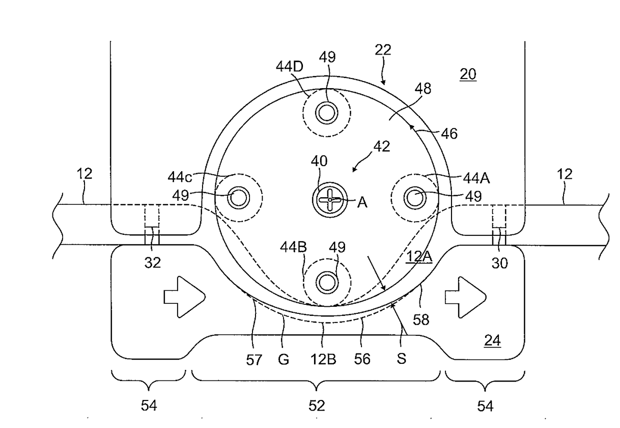
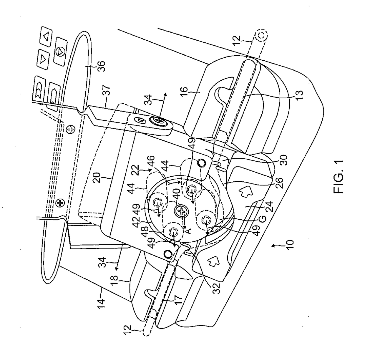
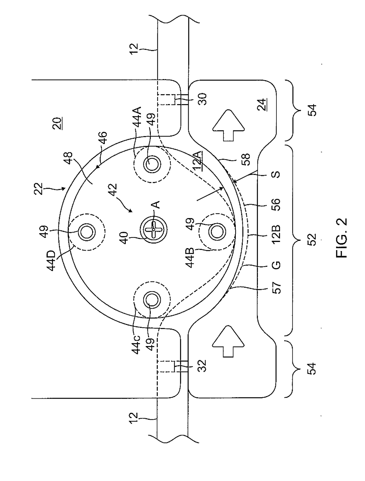
[0038]As shown in FIG. 1, the present invention includes a pump 10 configured to receive a tubing 12 (represented by broken lines for better clarity) for passing liquid therethrough by peristaltic action. The pump has a housing 14 configured with a suction port 18, a discharge port 16 and a rotor housing 20 therebetween. The tubing 12 extends through a channel 17 in the suction portion 18, the rotor housing 20, and a channel 13 in the discharge port 16. The rotor housing 20 includes a rotor 22, a roller bed 24, and an engagement member 26 supporting the roller bed 24, and intake and discharge tube clamps 32 and 30 on opposing sides of the rotor 22. The engagement member 26 extends from behind the rotor 22 and can be lifted and lowered relative to the rotor 22 by a handle 36 extending from a mounting bracket 37 that is pivotably coupled to an upper portion of the rotor housing 20 about axis 34 in moving the roller bed 24 and the clamps 30 and 32 relative to the rotor 22 between an op...


PUM


Abstract

A pump for use with a tube, having a rotor having an axis of rotation and a plurality of rollers configured to define an orbital path about the axis of rotation, the orbital path defined by a radius, and a roller bed having a surface adapted to support the tube for peristaltic compression by one or more rollers, wherein the surface has a predetermined profile comprising a circular arc segment and at least one side segment, the arc segment having a first curvature defined by the radius, and the at least one side segment having a second curvature lesser than the first curvature.

Description

FIELD OF INVENTION[0001]The present invention relates to an improved medical peristaltic pump.BACKGROUND[0002]Peristaltic pumps are a type of positive displacement pump used for pumping a variety of fluids. The fluid is contained within a flexible tube fitted inside a pump casing. The pump operates by peristalsis which is based on alternating compression and relaxation of the tube, drawing content in and propelling the content out. The peristaltic pump is therefore an accurate dosing pump, with an equal amount of liquid dosed each time.[0003]The liquid being pumped never comes into contact with any moving pump parts because it is contained within the tube. A conventional peristaltic pump includes one or more rotating shoes or rollers that pass along the length of tube throughout the pumping cycle, with each shoe or roller creating a total seal between suction side and discharge side of the pump. To prevent uncontrolled fluid backflow, at least one such roller must be compressing the...

Claims


Application Information

Patent Timeline
IPC IPC(8): F04B43/12F04B43/00
CPCF04B43/0072F04B43/1253F04B43/12
Inventor FANG, ITZHAKSZILAGYI, ANDREILIFSHITZ, ALEXANDERWALKER, JACKSULLIVAN, SEAN YASUO
Owner BIOSENSE WEBSTER (ISRAEL) LTD
Why Eureka
Try Eureka