

Reactor having iron core unit and coils, motor driver, power conditioner and machine
a technology of iron core unit and coil, which is applied in the direction of fixed inductance, basic electric elements, inductance, etc., can solve the problems of increasing structure size, and achieve the effects of reducing the size and manufacturing cost of the reactor, preventing an increase in the temperature of the coil, and enhancing the cooling
- Summary
- Abstract
- Description
- Claims
- Application Information
AI Technical Summary
Benefits of technology
Problems solved by technology
Method used
Image

Examples
first embodiment
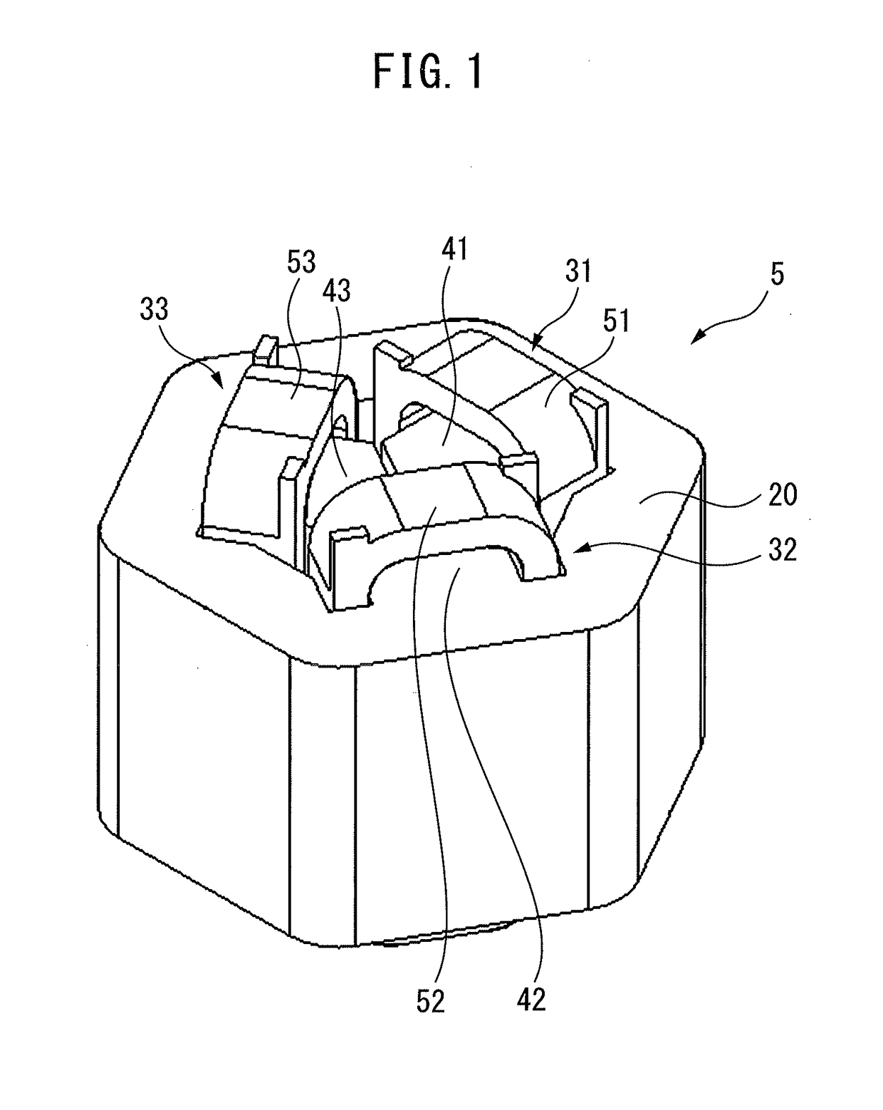
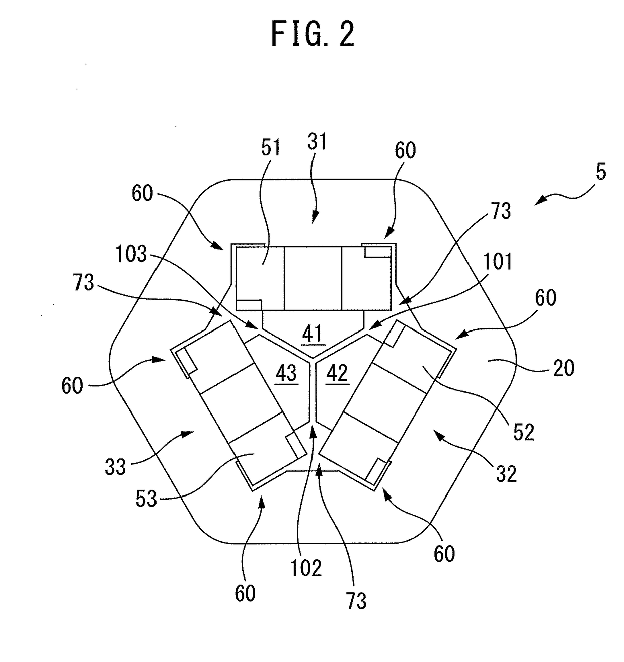
[0021]FIG. 1 is a perspective view of a reactor according to a FIG. 2 is an end face view of the reactor shown in FIG. 1. As shown in FIGS. 1 and 2, a reactor 5 includes an outer peripheral iron core 20 having a hexagonal cross-section and at least three iron-core coils 31 to 33 that contact or are connected to an inner surface of the outer peripheral iron core 20. The number of the iron-core coils is preferably an integral multiple of 3, and the reactor 5 can be thereby used as a three-phase reactor. Note that, the outer peripheral iron core 20 may have a round or other polygonal shape.
[0022]The iron-core coils 31 to 33 include iron cores 41 to 43 and coils 51 to 53 wound onto the iron cores 41 to 43, respectively. Note that, the outer peripheral iron core 20 and the iron cores 41 to 43 are each made by stacking iron sheets, carbon steel sheets or electromagnetic steel sheets, or made of a pressed powder core.
[0023]As is apparent from FIG. 2, the iron cores 41 to 43 have approxima...
second embodiment
[0032]FIG. 4 is an end face view of a reactor according to a A reactor 5 shown in FIG. 4 includes an outer peripheral iron core 20 and four iron-core coils 31 to 34 that are magnetically connected to the outer peripheral iron core 20. The number of the iron-core coils is preferably an even number of 4 or more, and the reactor 5 can be thereby used as a single-phase reactor.
[0033]In FIG. 4, the iron-core coils 31 to 34 are arranged inside the octagonal outer peripheral iron core 20. Note that, the outer peripheral iron core 20 may be round in shape. The iron-core coils 31 to 34 are arranged at approximately equal intervals in a circumferential direction of the reactor 5.
[0034]As is apparent from the drawing, the iron-core coils 31 to 34 include iron cores 41 to 44 extending in a radial direction and coils 51 to 54 wound onto the iron cores 41 to 44, respectively. Each of the iron cores 41 to 44 contacts the outer peripheral iron core 20 or is formed integrally with the outer periphe...
third embodiment
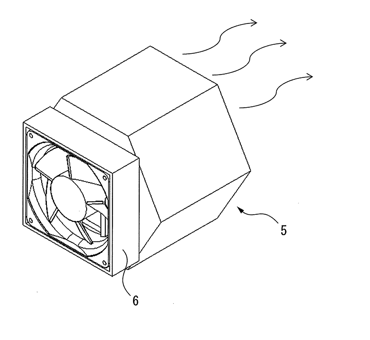
[0040]A reactor 5 described below may be any of a three-phase reactor and a single-phase reactor. FIGS. 5A and 5B are perspective views of a reactor according to a In FIG. 5A, a reactor 5 is disposed such that its axial direction coincides with the horizontal direction. In FIG. 5B, the reactor 5 is disposed such that its axial direction coincides with the vertical direction. In the drawings, a cooling fan 6 is attached to an end face of the reactor 5. The cooling fan 6 is driven by a non-illustrated motor.
[0041]When the cooling fan 6 is driven, air flows from the cooling fan 6 through spaces 70 and / or gaps 101 to 104 of the reactor 5 in the axial direction of the reactor 5. Therefore, the cooling effect on the coils 51 to 54 of the reactor 5 is further enhanced.
[0042]FIG. 6A is an exploded perspective view of a reactor according to a fourth embodiment, and FIG. 6B is a side view of the reactor according to the fourth embodiment. As shown in the drawings, end plates 81 and 82 are fi...
PUM
 Abstract
Description
Claims
Application Information