
Slot coupled directional coupler and directional filters in multilayer substrate

a directional coupler and multi-layer substrate technology, applied in coupling devices, waveguide type devices, basic electric elements, etc., can solve the problems of narrow bandwidth less than 2%, limited number of practical applications, bulky and heavy, etc., to reduce reflection loss and/or noise, and increase the directivity of signals

Active Publication Date: 2018-08-16
ZHANG YIFEI +3
View PDF1 Cites 8 Cited by
  • Summary
  • Abstract
  • Description
  • Claims
  • Application Information

AI Technical Summary

Benefits of technology

The patent text describes how directional filters and couplers are designed to minimize signal loss and noise, and improve the accuracy and direction of signals. This technology can be useful in a variety of applications, such as wireless communication and medical imaging.

Problems solved by technology

Various DFs have been devised; however, a limited number of them have found practical applications.
Typically, it is bulky and heavy, and has a narrow bandwidth of less than 2%.
However, tiny coupling gaps between the resonators and terminating lines are critically desired to provide sufficient coupling, which is extremely challenging for the commercially available circuit printing technologies, particularly when fabricating the devices for applications at high frequencies.
However, the traveling-wave DFs suffer from the same fabrication tolerance problem as the standing-wave DFs as the frequency increases.
As the frequency increases to W-band, i.e., 75-110 GHz, it becomes increasingly critical to obtain sufficient coupling between resonators and terminating lines with planar structures, leading to significant insertion loss.
In these structures, the resonators and terminating lines are overlapped vertically, which may enhance the coupling, but may introduce large reflection and insertion loss.
The coupling efficiency of the traditional multilayer quarter-wavelength directional coupler is strongly limited by the thickness of the substrates.
Thus, it is challenging to scale these multilayer DFs to higher frequencies due to the limited available thickness of the circuit substrate.

Method used


Image

  • Slot coupled directional coupler and directional filters in multilayer substrate
  • Slot coupled directional coupler and directional filters in multilayer substrate
  • Slot coupled directional coupler and directional filters in multilayer substrate

Examples


Embodiment Construction

[0043]The present disclosure now will be described more fully hereinafter with reference to the accompanying drawings, in which various embodiments are shown. The invention may, however, be embodied in many different forms and should not be construed as limited to the example embodiments set forth herein. These example embodiments are just that—examples—and many implementations and variations are possible that do not require the details provided herein. It should also be emphasized that the disclosure provides details of alternative examples, but such listing of alternatives is not exhaustive. Furthermore, any consistency of detail between various examples should not be interpreted as requiring such detail—it is impracticable to list every possible variation for every feature described herein. The language of the claims should be referenced in determining the requirements of the invention.

[0044]It will be appreciated that the use of the same or similar reference numerals indicates t...


PUM


Abstract

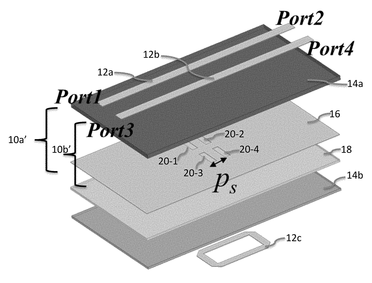
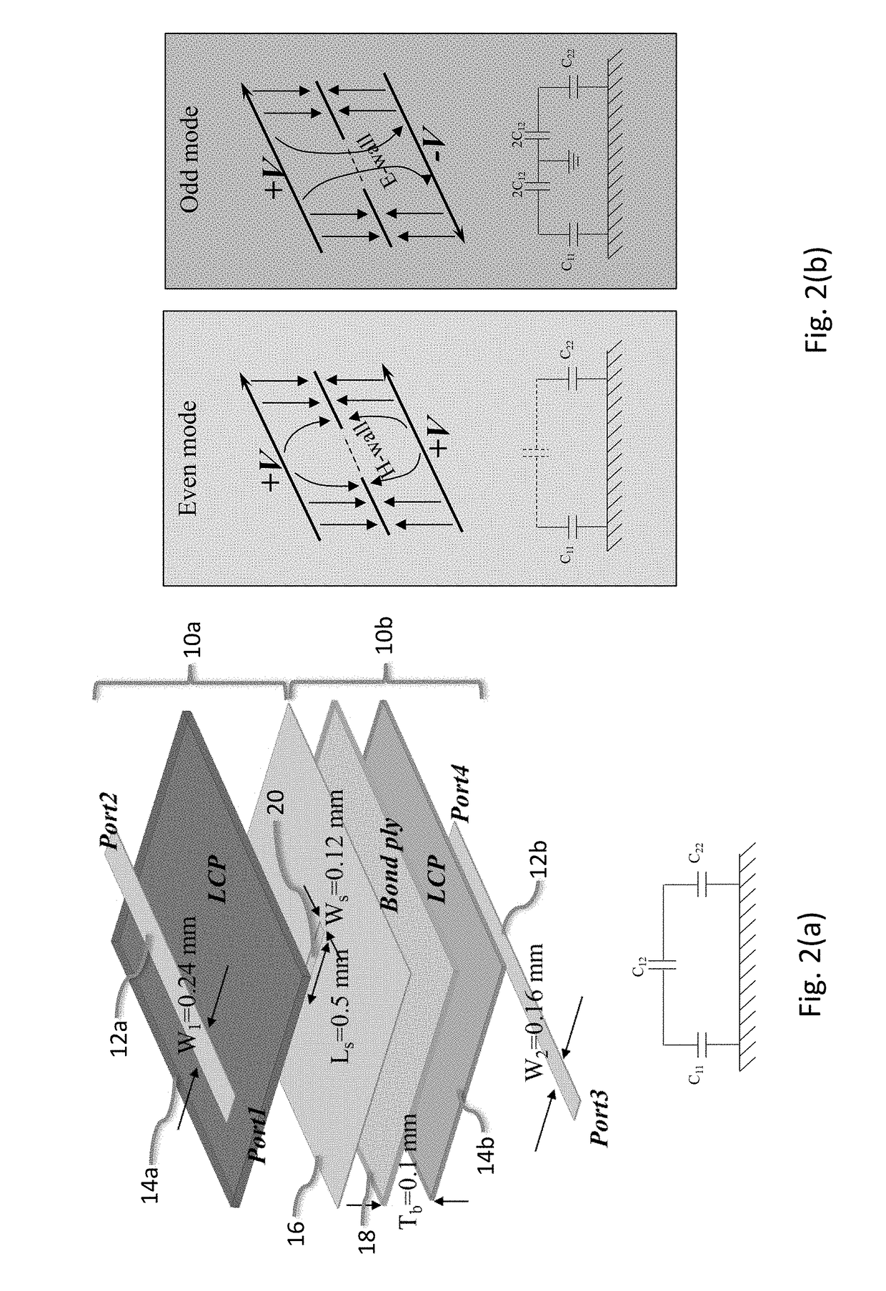
Traveling-wave directional filters (DFs) with multiple coupling slots are disclosed. A traveling-wave directional filter may include two terminating conductive strips in a top circuit layer of a substrate, a loop resonator in a bottom layer of a substrate, and a shared ground plane. Coupling slots in the ground plane may couple the conductive strips via the loop resonator.

Description

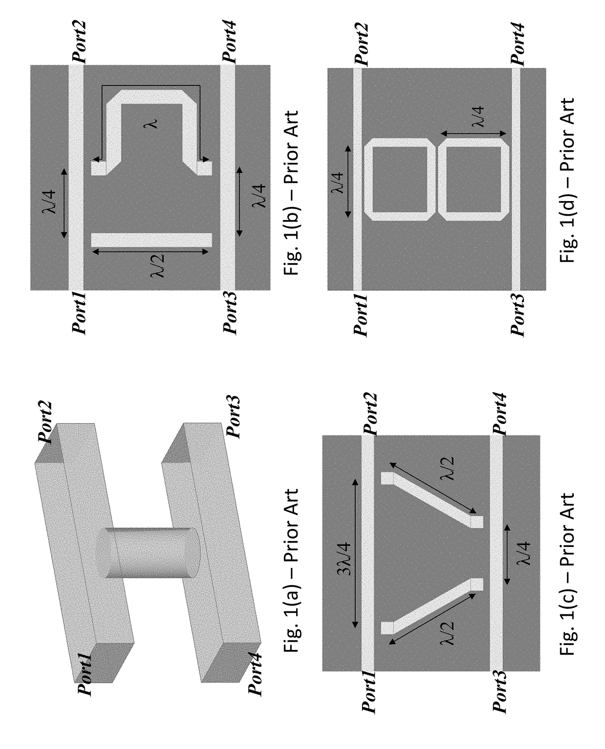
CROSS-REFERENCE TO RELATED APPLICATIONS[0001]This U.S. non-provisional patent application claims priority under 35 U.S.C. § 119 to U.S. provisional patent application No. 62 / 457,617, filed on Feb. 10, 2017, with the United States Patent and Trademark Office, the entire contents of which are hereby incorporated by reference.BACKGROUND[0002]Directional filters (DFs) have gained interest in the applications of frequency division multiplexing and system stability improvement at circuit level. They may act either as channel combiners or channel separators. DFs address miniaturization and low reflection requirements of various implementations. Various DFs have been devised; however, a limited number of them have found practical applications.[0003]FIGS. 1(a), 1(b), 1(c) and 1(d) show various examples of prior art DFs. For example, a broadband signal fed into Port 1 of the DFs shown in FIGS. 1(a)-(d) will be isolated at Port 4 (“isolated” indicating the signal is substantially not sent to P...

Claims


Application Information

Patent Timeline
Patent Type & Authority Applications(United States)
IPC IPC(8): H01P1/212H01P5/18
CPCH01P1/212H01P5/184H01P5/185H01P5/187
Inventor ZHANG, YIFEISHI, SHOUYUANMARTIN, RICHARDPRATHER, DENNIS
Owner ZHANG YIFEI
Features
  • Generate Ideas
  • Intellectual Property
  • Life Sciences
  • Materials
  • Tech Scout
  • Unparalleled Data Quality
  • Higher Quality Content
  • 60% Fewer Hallucinations
Learn More